Mechanical coupling arrangement for a lattice support beam

a technology of mechanical coupling and lattice support, which is applied in the direction of girders, rod connections, other domestic objects, etc., can solve the problems of low load bearing capacity, members to aluminium chord members suffer from severe weakening of the material in the heat affected zone, and relatively low load bearing capacity

Active Publication Date: 2013-11-28
PLUSEIGHT TECH AB
View PDF5 Cites 4 Cited by
  • Summary
  • Abstract
  • Description
  • Claims
  • Application Information

AI Technical Summary

Benefits of technology

[0023]The mechanical coupling arrangement further advantageously comprises a second diagonal member made of extruded aluminium profile, said connector element further comprises a third attachment portion having a third contact surface in contact with an abutment surface of said second diagonal member, and said third contact surface is pressed against said abutment surface of said second diagonal member by means of at least one fastener, whose longitudinal direction is substantially parallel with a longitudinal direction of said second diagonal member. A mechanical coupling arrangement connecting two diagonal members to a chord member, wherein each diagonal member has an individual orientation is a favourable alternative if the diagonal members are closely arranged. A connector element for a single diagonal member is more favourable if the diagonal members are arranged more distributed.

Problems solved by technology

The disadvantage with this design is low load bearing capacity, at least when aluminium is used.
Coupling arrangements of lattice beams joined by welding of aluminium diagonal members to aluminium chord members suffer from severely weakening of the material in the heat affected zone, both in short term as well as long term due to fatigue.
Hence, the allowed stresses in the heat affected zone are very limited, resulting in a relatively low load bearing capacity.
Both alternatives however lead to increased weight of the lattice beam.
Mechanical play in the coupling arrangement leads to reduced load bearing capacity because said mechanical play accumulates from each coupling arrangement and results in increased beam deflection under high load, leading to weakening of the beam strength, as well as affecting the natural frequency of the lattice beam.

Method used


Image

  • Mechanical coupling arrangement for a lattice support beam
  • Mechanical coupling arrangement for a lattice support beam
  • Mechanical coupling arrangement for a lattice support beam

Examples


Embodiment Construction

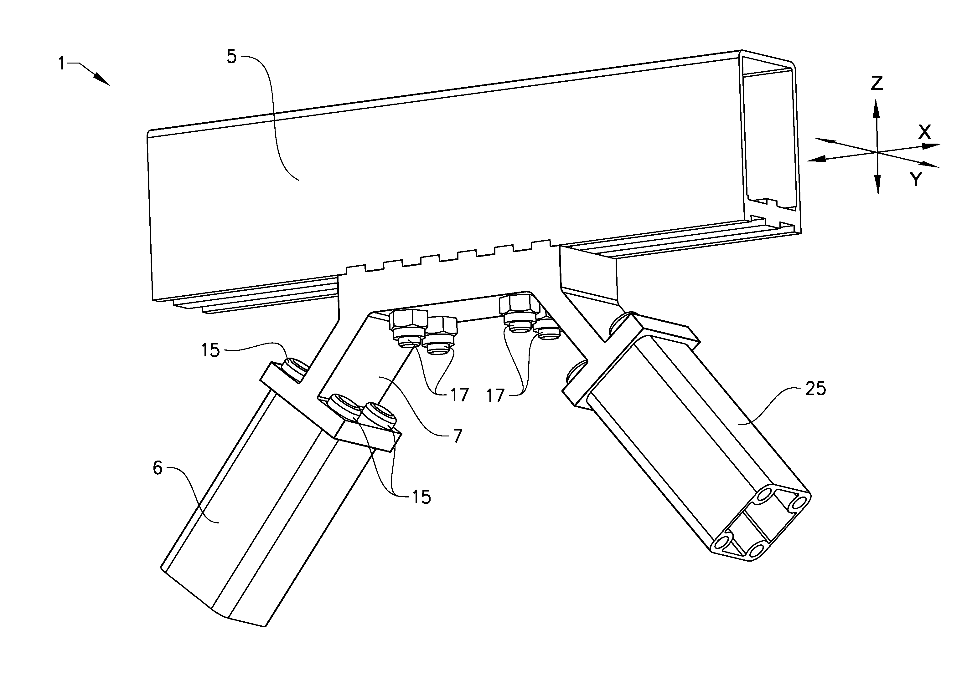
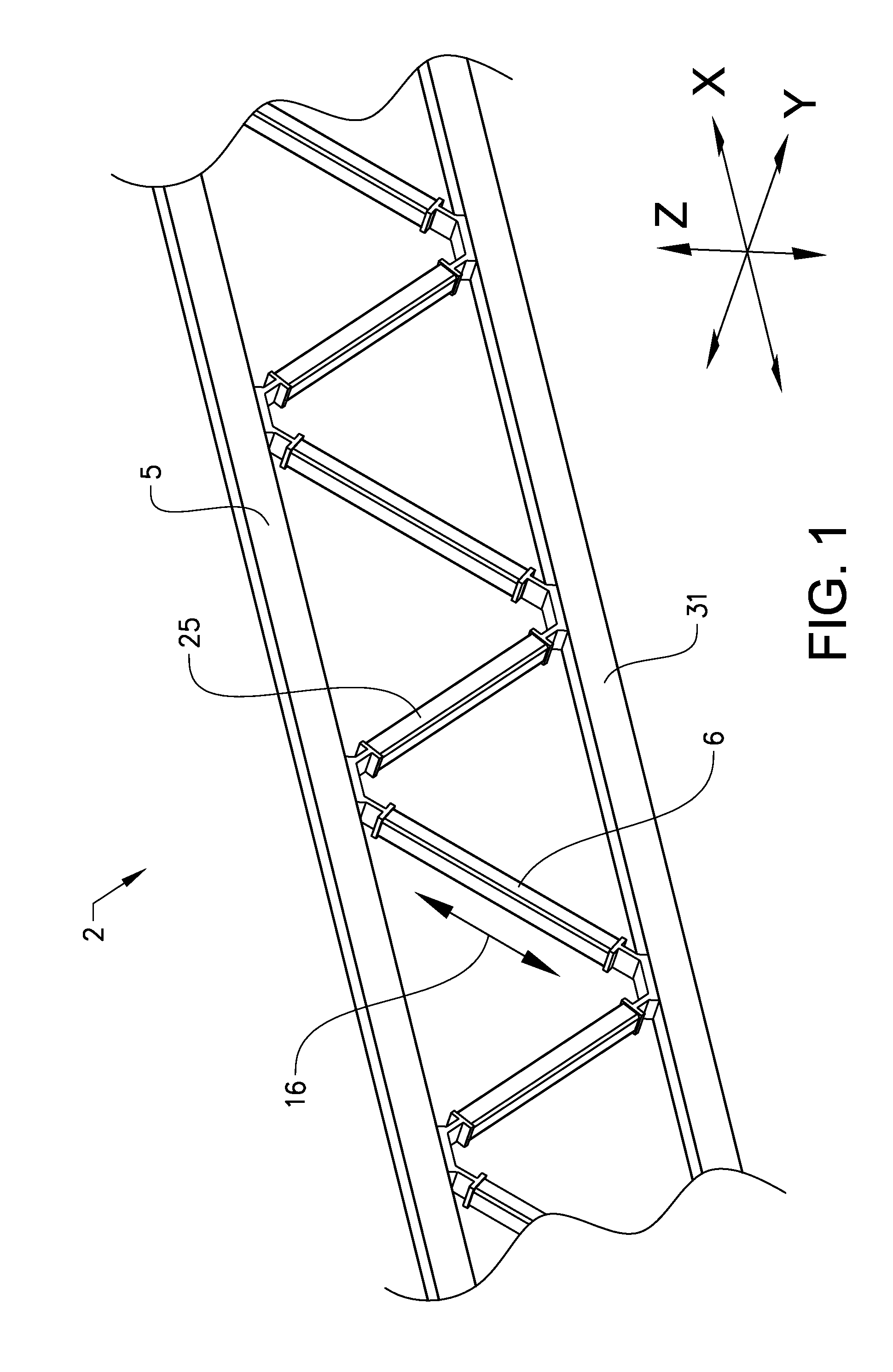
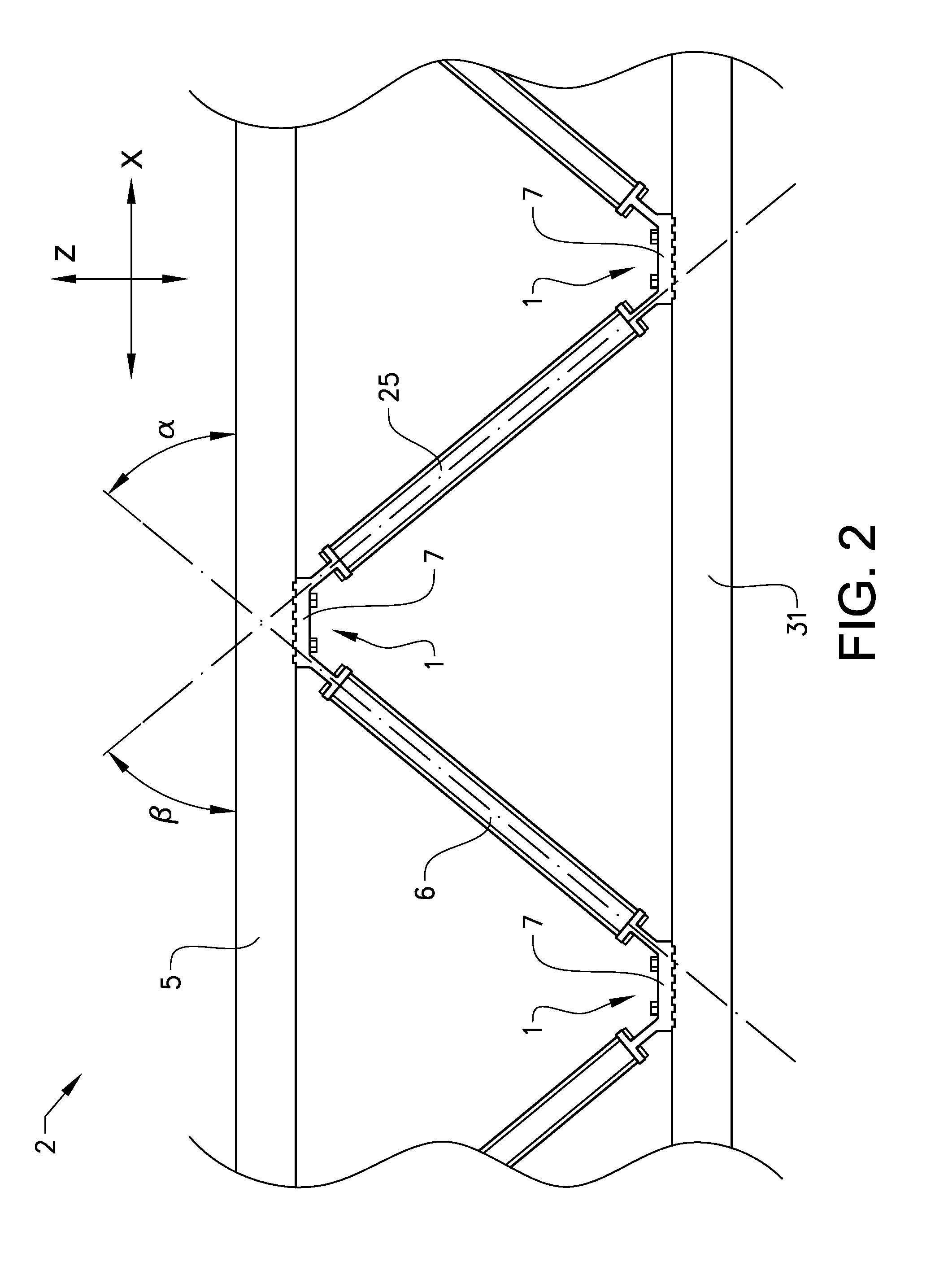
[0034]FIG. 1 shows schematically a aluminium lattice support beam 2 according to the invention, comprising a first chord member 5, a second chord member 31, and a plurality of diagonal members 6, 25 interconnecting said first and second chord members 5, 31. Mechanical coupling arrangements 1 are provided for connecting each of said chord members 5, 31 with corresponding diagonal member 6, 25. Each of the mechanical coupling arrangements 1 comprises a longitudinal direction X, a transverse direction Y perpendicular to the longitudinal direction X, and a web direction Z perpendicular to both the longitudinal direction X and the transverse direction Y. The longitudinal direction X and the web direction Z together define a first plane, which may also be labelled vertical plane in case the support beam 2 is essentially two-dimensional and arranged upright with the first chord member 5 on top of the second chord member 31. When the lattice support beam comprises two straight and parallel ...


PUM

PropertyMeasurementUnit
inclination angleaaaaaaaaaa
contact surfaceaaaaaaaaaa
transverse lengthaaaaaaaaaa

Abstract

Disclosed herein is a mechanical coupling arrangement for a lattice support beam having a longitudinal direction and a transverse direction, said mechanical coupling arrangement comprising at least a first chord member, a first diagonal member, and a connector element for joining said first chord member with said first diagonal member, wherein each of said first chord member, said first diagonal member, and said connector element is made of extruded aluminum profile, said connector element comprising at least a first attachment portion having a first contact surface in contact with said first chord member, and a second attachment portion having a second contact surface in contact with an abutment surface of said first diagonal member.

Description

TECHNICAL FIELD[0001]The present invention relates to a mechanical coupling arrangement for a lattice support beam having a longitudinal direction and a transverse direction, and a method for manufacturing such a coupling arrangement. The mechanical coupling arrangement comprising at least a first chord member, a first diagonal member, and a connector element for joining said first chord member with said first diagonal member.BACKGROUND ART[0002]Lattice beams are traditionally made by welding together chord members with diagonal members. Prior art document GB 927,917 discloses a welded, three-dimensional lattice girder consisting of rod-like members, wherein the materials suitable for making the panel-type lattice girder include steel, aluminium, plastic and any other weldable material. The disadvantage with this design is low load bearing capacity, at least when aluminium is used.[0003]There is thus a need for an improved lightweight lattice beam removing the above mentioned disadv...

Claims


Application Information

Patent Timeline
Patent Type & Authority Applications(United States)
IPC IPC(8): E04B1/41E04C3/02B23P15/00
CPCE04B1/40B23P15/00E04C3/02E04C3/08E04C2003/0491F16B7/0486F16B7/185Y10T29/49625F16B2200/67E04B1/24E04B2001/2406E04B1/388
Inventor WALLTHER, HARRY
Owner PLUSEIGHT TECH AB
Why Eureka
Try Eureka