Liquid Vapor Phase Separation Apparatus

a technology of liquid vapor phase and separation apparatus, which is applied in separation processes, lighting and heating apparatus, vortex flow apparatus, etc., can solve the problems of transport refrigeration system size restrictions, transport refrigerant vapor compression systems are subject to vibration and movement,

Active Publication Date: 2013-11-28
CARRIER CORP
View PDF7 Cites 20 Cited by
  • Summary
  • Abstract
  • Description
  • Claims
  • Application Information

AI Technical Summary

Problems solved by technology

Being mobile, transport refrigerant vapor compression systems are subject to vibration and movements not experienced by stationary refrigerant vapor compression systems.
Transport refrigeration systems are also subject to

Method used


Image

  • Liquid Vapor Phase Separation Apparatus
  • Liquid Vapor Phase Separation Apparatus
  • Liquid Vapor Phase Separation Apparatus

Examples


Embodiment Construction

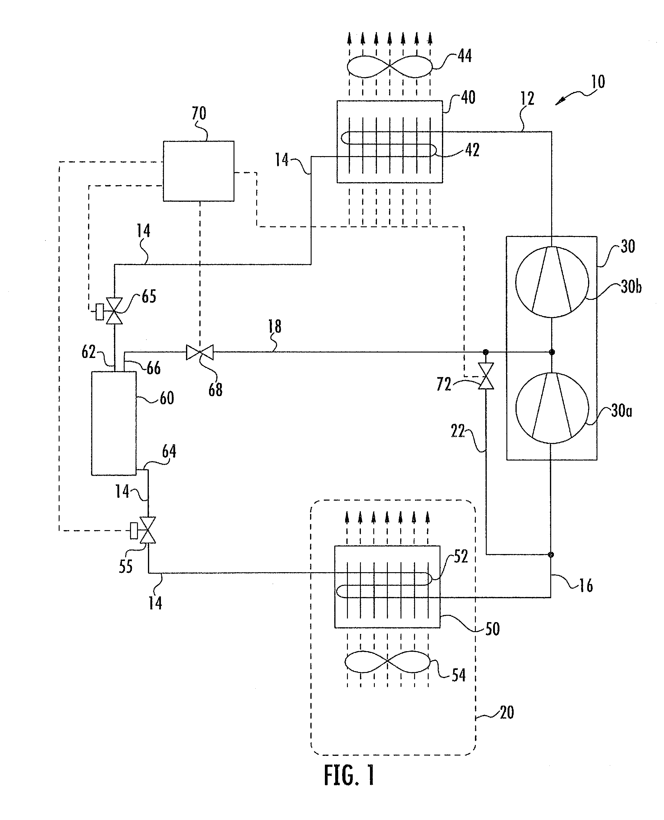
[0021]Referring now to FIG. 1, there is depicted therein an exemplary embodiment of a refrigerant vapor compression system 10 suitable for use in a transport refrigeration system for refrigerating the atmosphere within the temperature controlled cargo space 20 of a truck, trailer, container or other mobile refrigeration system for transporting perishable goods, fresh or frozen. The refrigerant vapor compression system 10 is particularly adapted for operation in a transcritical cycle with a low critical temperature refrigerant, such as for example, but not limited to, carbon dioxide. In the depicted embodiment, the refrigerant vapor compression system 10 includes a multi-step compression device 30, a refrigerant heat rejection heat exchanger 40 and a refrigerant heat absorption heat exchanger 50, also referred to herein as an evaporator, with refrigerant lines 12, 14 and 16 connecting the aforementioned components in refrigerant flow communication in a refrigerant circuit.

[0022]A pri...


PUM

PropertyMeasurementUnit
Diameteraaaaaaaaaa
Volumeaaaaaaaaaa
Areaaaaaaaaaaa

Abstract

A phase separation apparatus is provided for separating a two-phase fluid flow into a liquid phase portion and a vapor phase portion. The phase separation apparatus may be applied to the separation of a two-phase refrigerant flow in a refrigerant vapor compression system operating in a transcritical cycle.

Description

CROSS REFERENCE TO RELATED APPLICATION[0001]This application claims priority to U.S. Provisional Patent Application Ser. No. 61 / 442,541 entitled “Liquid Vapor Phase Separation Apparatus” filed on Feb. 14, 2011. The content of this application is incorporated herein by reference in its entirety.BACKGROUND OF THE INVENTION[0002]This invention relates generally to liquid vapor phase separation and, more particularly, to the separation of a two-phase refrigeration flow into a liquid phase portion and a vapor phase portion in a refrigerant vapor compression system having a flash tank economizer and operating in a transcritical cycle.[0003]Refrigerant vapor compression systems are well known in the art and commonly used in mobile refrigeration systems, such as transport refrigeration systems for refrigerating air or other gaseous fluid supplied to a temperature controlled cargo space of a truck, trailer, container or the like for transporting perishable items, fresh or frozen, by truck, r...

Claims


Application Information

Patent Timeline
IPC IPC(8): B01D45/16
CPCB01D45/16B60H1/3228F25B1/10F25B43/00F25B2400/02F25B2600/026F25B2600/2509F25B2600/2513F25B41/39
Inventor HUFF, HANS-JOACHIMLAMENDOLA, KURSTENASPROVSKI, ZVONKO
Owner CARRIER CORP
Why Eureka
Try Eureka