Article Transport Facility

a technology for transporting facilities and articles, applied in the direction of transportation and packaging, conveying, elevated railways, etc., can solve the problems of difficult implementation of options, difficult to cause the article transport vehicle to travel at higher speeds, and the entire facility becomes expensive, so as to reduce the speed of article transporting, reduce the effect of article transporting efficiency and improve the effect of transporting efficiency

Active Publication Date: 2013-11-28
DAIFUKU CO LTD
View PDF9 Cites 17 Cited by
  • Summary
  • Abstract
  • Description
  • Claims
  • Application Information

AI Technical Summary

Benefits of technology

The technical effect of this patent is to improve article transporting efficiency in existing transport facilities by providing a rotatable member transporting device in specific sections of the predetermined travel path where higher travel speeds are needed. This avoids the decrease in travel speed when the article transport vehicle travels in the ascending path portion only with the propelling force obtained by drivingly rotating the propelling rotatable member provided to the article transport vehicle.

Problems solved by technology

And work zone travel path portions are installed with curved path portions in many cases, making it difficult to cause the article transport vehicle to travel at higher speeds.
In this case, however, because the article transport vehicle is provided with a large and expensive electric motor, there is a disadvantage that the entire facility becomes expensive, which makes this a difficult option to implement.
And the entire facility becomes expensive if each of the many article transport vehicles is equipped with such an expensive electric motor.
Thus, there is also a disadvantage that the entire facility becomes expensive as the result of the increased installation cost of the travel rails.
In such cases, it is difficult in practice to convert existing article transport vehicles so that they can travel at higher speeds.
Thus, it may be impossible to cause the article transport vehicle to travel at higher speeds in existing article transport facilities.

Method used


Image

  • Article Transport Facility
  • Article Transport Facility
  • Article Transport Facility

Examples


first embodiment

[0084]The first embodiment of an article transport facility in accordance with the present invention is described with reference to the drawings.

(Overall Structure of the Article Transport Facility)

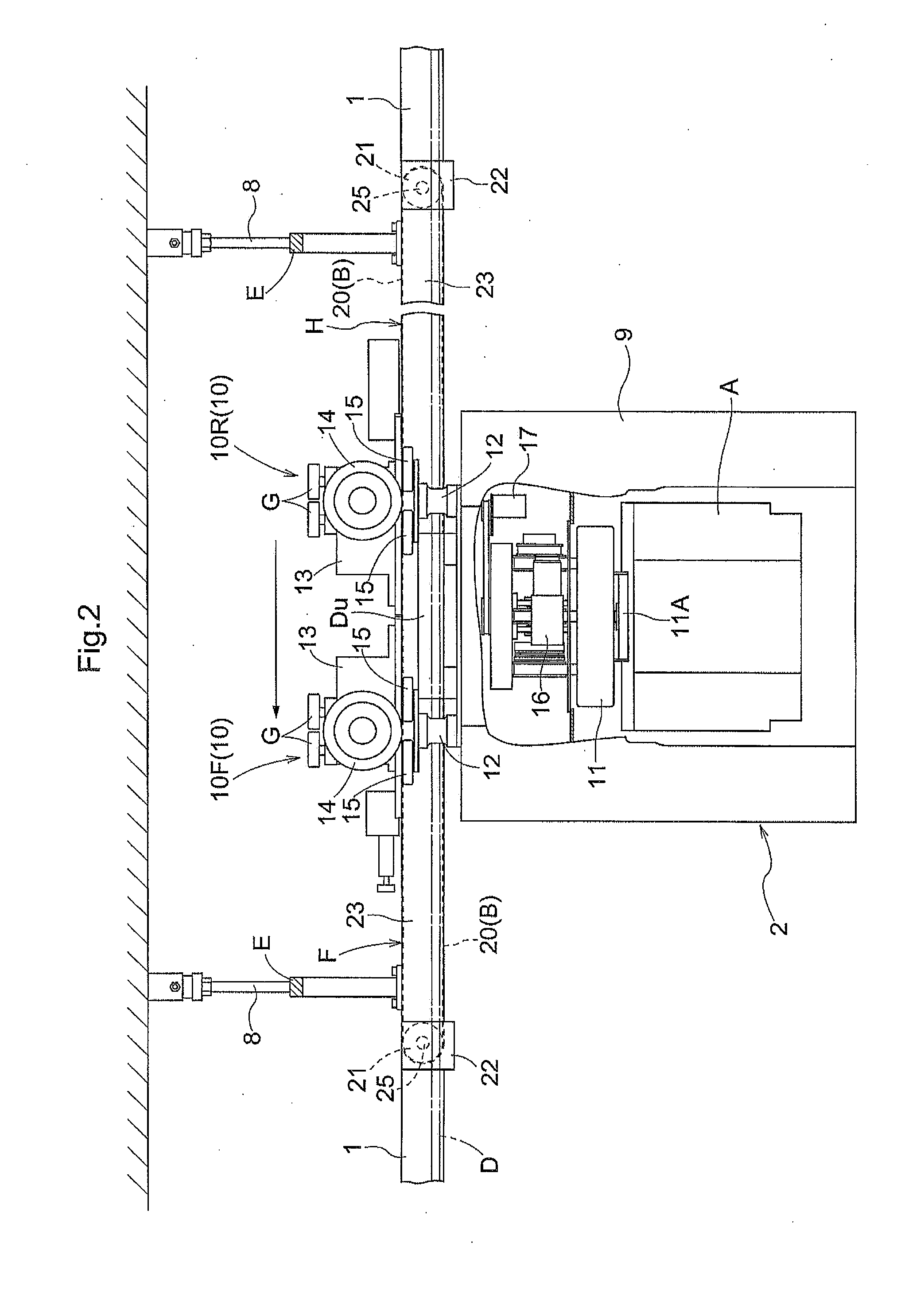
[0085]As shown in FIGS. 2 and 3, a pair of right and left travel rails 1 are installed on the ceiling side of, for example, a clean room and extend along predetermined travel paths L (see FIG. 1). And hoist-type article transport vehicles 2 are provided which are configured to travel along the predetermined travel paths L while guided by the travel rails 1.

[0086]In the present embodiment, each article transport vehicle 2 is configured to transport, as an article A, a container for storing or carrying semiconductor substrates.

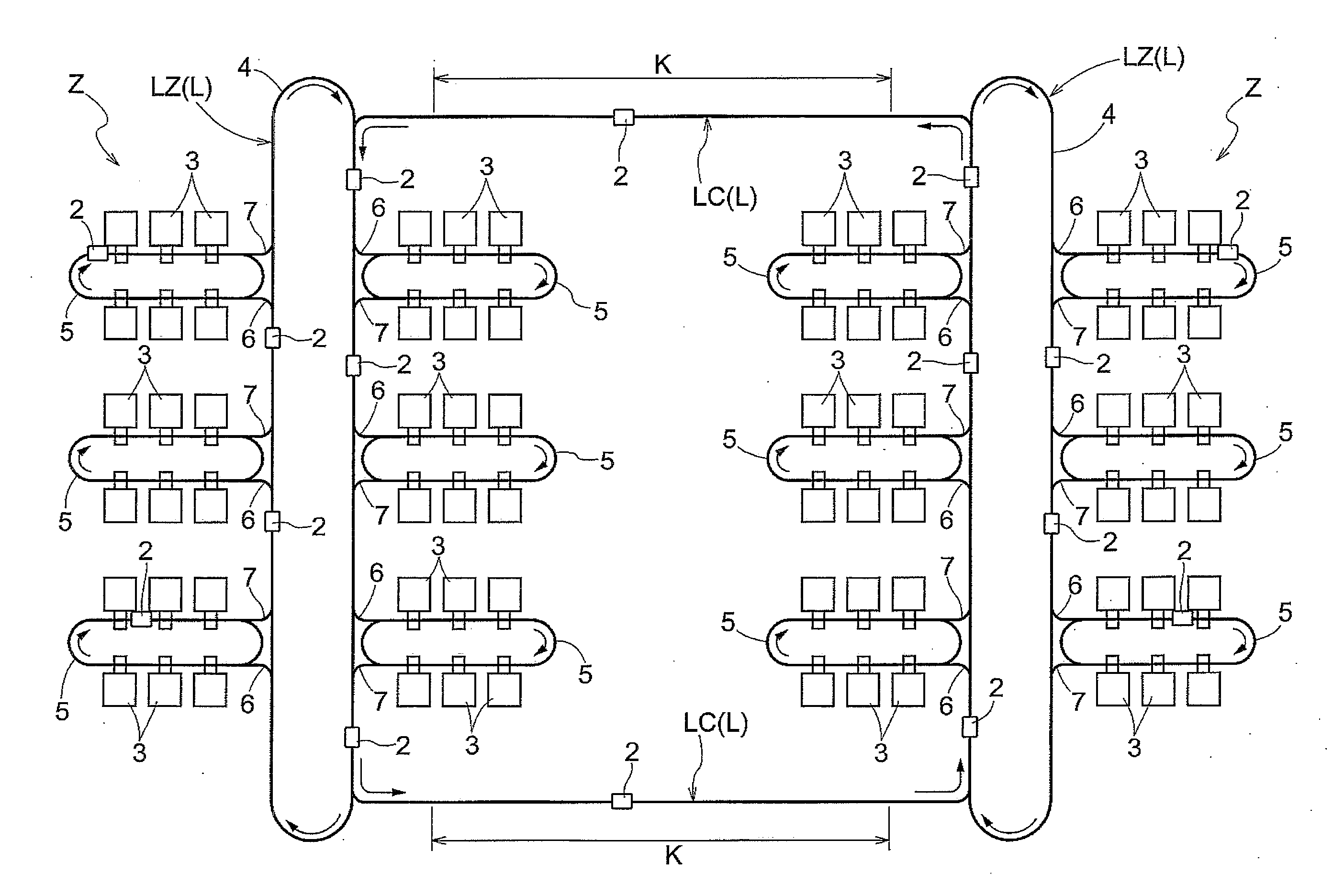
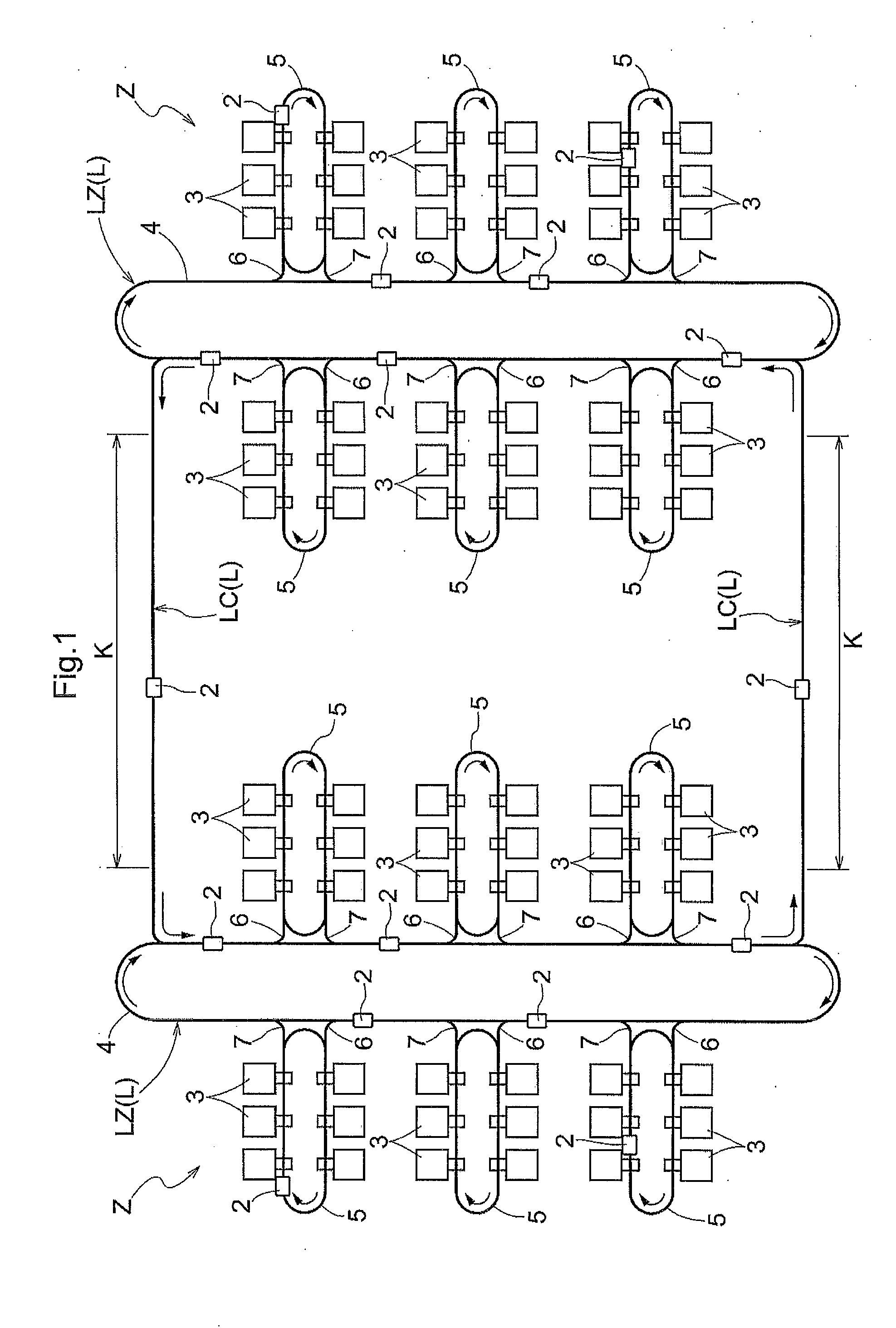
[0087]As shown in FIG. 1, the predetermined travel paths L are installed so as to extend along, or by way of, a plurality of article processors 3 for processing the semiconductor substrates.

[0088]In the present embodiment, a pair of work zones Z are provided as a plur...

second embodiment

[0149]The second embodiment is described next, which has a configuration similar to that of the first embodiment except that the configuration of the rotatable member transporting device F is different from that in the first embodiment.

[0150]Therefore, only the configuration of the rotatable member transporting device F is described here in order not to duplicate the descriptions of other parts.

[0151]In the second embodiment, the rotatable member transporting device F utilizes transporting belts B for supporting and transporting the travel wheels 14 of the article transport vehicle 2 as is the case in the first embodiment; however, the configuration of the transporting belts B is different from that in the first embodiment.

[0152]More specifically, as shown in FIG. 9, the rotatable member transporting device F includes, on each lateral side: an entrance side transporting belt 30 which functions as an entrance side transporting member in the entrance side portion Kf of the specific se...

third embodiment

[0169]The third embodiment is described next, which has a configuration similar to that of the first embodiment except that the configuration of the rotatable member transporting device F is different from that in the first embodiment.

[0170]Therefore, only the configuration of the rotatable member transporting device F is described here in order not to duplicate the descriptions of other parts.

[0171]In the third embodiment, the rotatable member transporting device F includes and utilizes transporting belts B for supporting and transporting the travel wheels 14 of the article transport vehicle 2 similarly to the first embodiment. In addition, each transporting belt B includes the entrance side transporting belt 30, the intermediate transporting belt 31, and the exit side transporting belt 32 similarly to the second embodiment. However, the configurations of the entrance side transporting belt 30 and the exit side transporting belt 32 in the third embodiment are different from those i...


PUM


Abstract

An article transport facility includes an article transport vehicle and a rotatable member transporting device. The article transport vehicle is configured to travel along a predetermined travel path by obtaining propelling force by drivingly rotating a propelling rotatable member with the propelling rotatable member in contact with a contact portion. The propelling rotatable member can be in contact with the rotatable member transporting device. And the rotatable member transporting device transports, in an advancing direction, the propelling rotatable member in contact with the rotatable member transporting device, and is provided in place of the contact portion in a specific section included in the predetermined travel path. The propelling rotatable member is configured to be able to be drivingly rotated while in contact with the rotatable member transporting device.

Description

FIELD OF THE INVENTION[0001]The present invention relates to an article transport facility having an article transport vehicle configured to travel along a predetermined travel path by obtaining propelling force by drivingly rotating a propelling rotatable member with the propelling rotatable member in contact with a contact portion.BACKGROUND[0002]In article transport facilities such as one described above, articles are transported by traveling article transport vehicles. There are article transport vehicles that are of a hoist type that travel in the ceiling area of work space, and that are of a carriage type that travel on the floor area of the work space.[0003]An example of an article transport facility disclosed in JP Publication of Application No. 2011-116313 (Patent Document 1) is one including an article transport vehicle of the hoist type that travels in a ceiling area of work space. In the example in Patent Document 1, the article transport vehicle travels in a ceiling are...

Claims


Application Information

Patent Timeline
IPC IPC(8): B65G35/06
CPCB65G35/06B60L5/005H01L21/67259H01L21/67706H01L21/67727H01L21/6773H01L21/67733H01L21/67736B60L2200/26B61B13/00B60L5/00B65G1/00B61B3/02
Inventor KASUYA, TORUSATOU, MASARU
Owner DAIFUKU CO LTD
Why Eureka
Try Eureka