Indicator light tower technology

a technology of indicator light tower and light tower, which is applied in the direction of semiconductor devices for light sources, lighting and heating apparatus, lighting applications, etc., can solve the problems of significant limitations and shortcomings of the existing technology in this field

Active Publication Date: 2013-11-28
CLORE LEE
View PDF5 Cites 39 Cited by
  • Summary
  • Abstract
  • Description
  • Claims
  • Application Information

AI Technical Summary

Benefits of technology

[0010]The present invention provides indicator apparatus and methods which are practical, reliable, acc

Problems solved by technology

Existing technology in this field is believed t

Method used


Image

  • Indicator light tower technology
  • Indicator light tower technology
  • Indicator light tower technology

Examples


Embodiment Construction

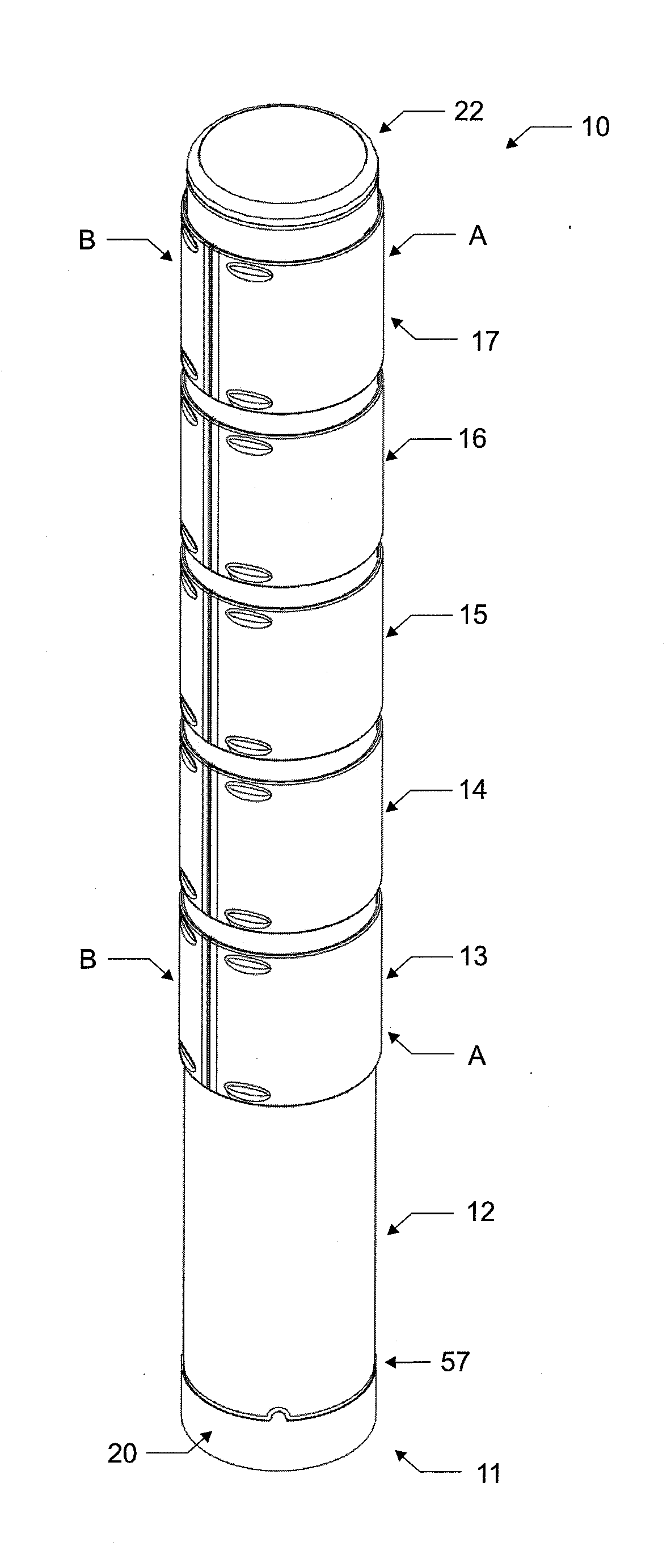
[0045]The exterior of indicator has a cylindrical or columnar configuration including transparent or translucent panels or lenses. The interior of the indicator is based on a flat, planar arrangement of light sources. The invention provides a means of translating the flat, essentially unidirectional or bidirectional arrangement of lights to a 180 to 360 degree, multidirectional light source. The preferred light sources are light emitting diodes LED's, preferably of single color in an illuminated segment. It is possible to have up to three (3) colors in a single segment. This would entail a bank of each Red, Yellow, and Green LEDs on both side of the PCB in a single illuminated segment where the lens is either clear with diffusing film or a diffusing polycarbonate (i.e. RTP resin). Only one (1) color would be active at any one time in such embodiment.

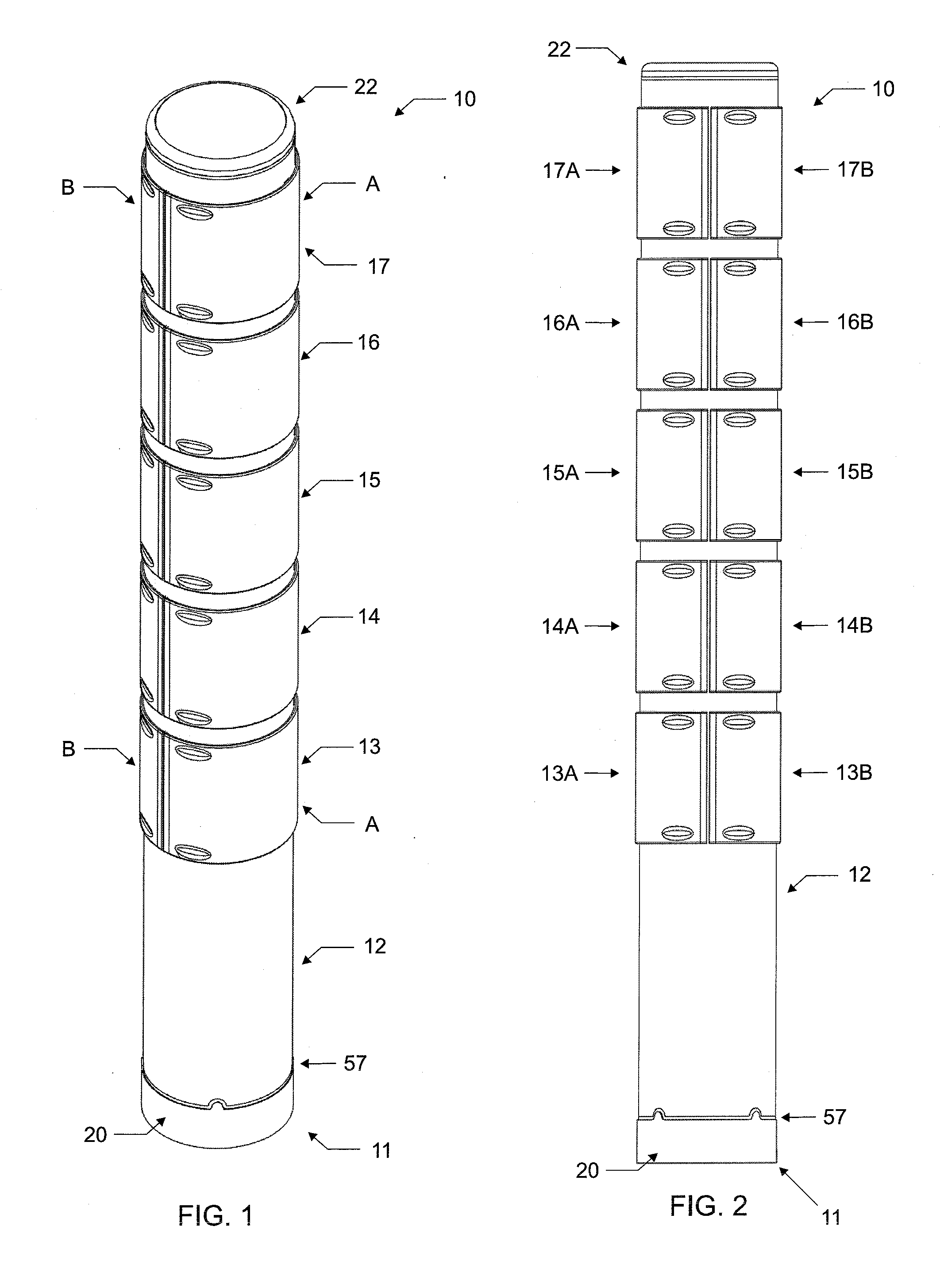
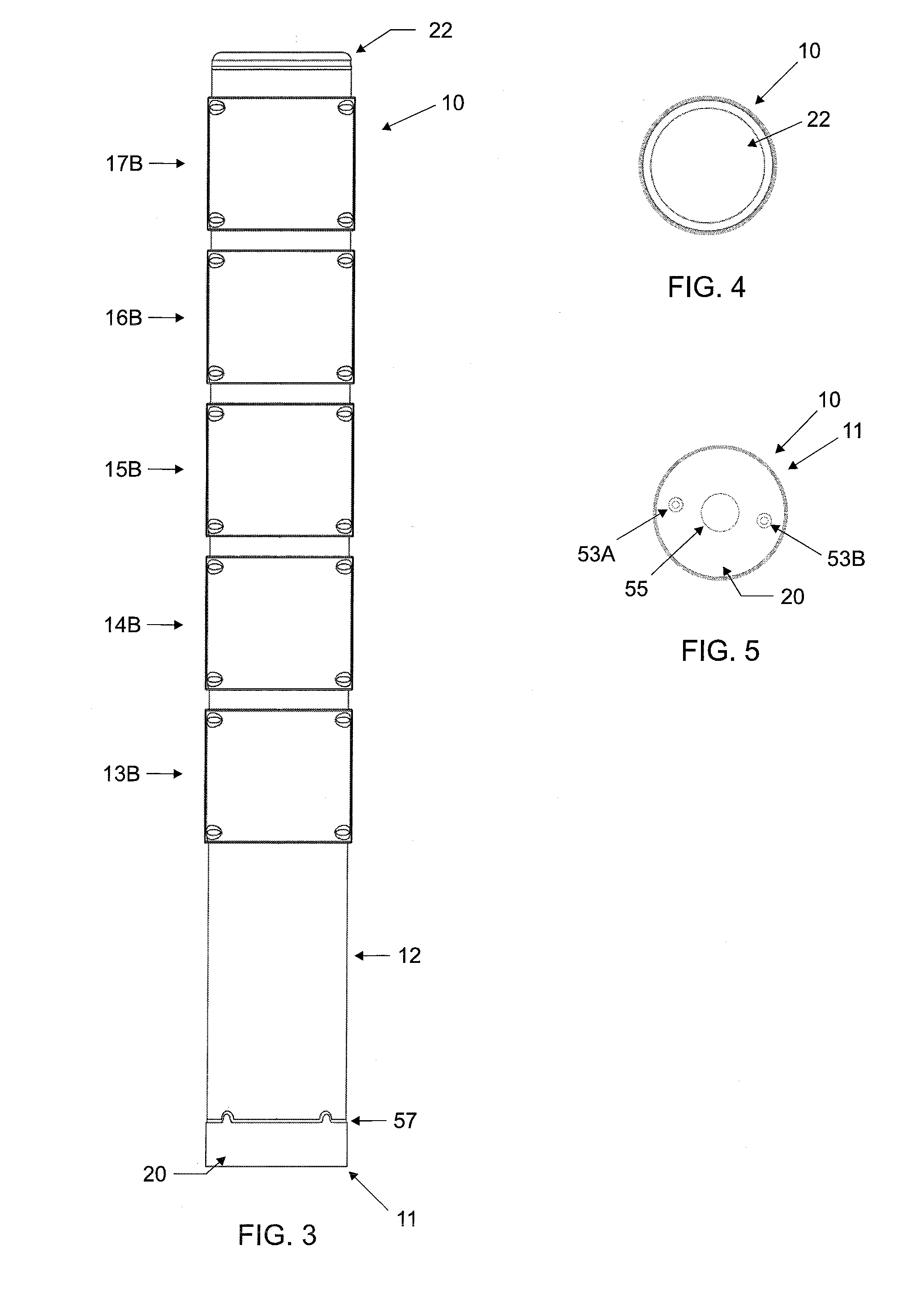
[0046]FIGS. 1-5 show an embodiment of the light tower 10 of the present invention. This embodiment of the light tower 10 has a flat cap...


PUM


Abstract

A light tower or stack light including an exterior which has a cylindrical or columnar configuration including transparent or translucent panels or lenses, and a interior based on a flat, planar arrangement of light sources. The light tower translates the flat, essentially unidirectional or bidirectional arrangement of lights to a 180 to 360 degree, multidirectional light source. The light indicator tower is for use with a industrial apparatus or process to indicate the status of the apparatus or process. The tower includes a flat, planar, PCB light panel having two sides, the light panel further having a plurality of LED light sources disposed on each side of the light panel. The tower has a curvilinear light dispersing lens disposed to disperse light over a range of 360 degrees.

Description

CROSS REFERENCE TO RELATED APPLICATIONS, IF ANY[0001]This application claims the benefit under 35 U.S.C. §119(e) of co-pending U.S. Provisional Patent Application Ser. No. 61 / 644,604, filed May 9, 2012, which is hereby incorporated by reference.37 C.F.R. §1.71(E) AUTHORIZATION[0002]A portion of the disclosure of this patent document contains material which is subject to copyright protection. The copyright owner has no objection to the facsimile reproduction by anyone of the patent document or the patent disclosure, as it appears in the US Patent and Trademark Office patent file or records, but otherwise reserves all copyright rights whatsoever.STATEMENT REGARDING FEDERALLY SPONSORED RESEARCH OR DEVELOPMENT[0003]Not applicable.REFERENCE TO A MICROFICHE APPENDIX, IF ANY[0004]Not applicable.BACKGROUND OF THE INVENTION[0005]1. Field of the Invention[0006]The present invention relates, generally, to indicator and signaling systems, apparatus and methods. Particularly, the invention relat...

Claims


Application Information

Patent Timeline
IPC IPC(8): F21V5/04H05B44/00
CPCF21V5/04F21V33/0052H04R1/028F21W2111/00F21Y2105/10F21Y2115/10F21Y2107/90H05B45/46
Inventor CLORE, LEE
Owner CLORE LEE
Why Eureka
Try Eureka