Gas laser device

a laser device and gas technology, applied in the direction of laser details, active medium materials, electrical devices, etc., can solve the problems of degrading the working efficiency of laser processing, changing the gas pressure in the laser gas vessel, etc., and achieve the effect of reducing the rotation number of the blower

Inactive Publication Date: 2013-11-28
FANUC LTD
View PDF8 Cites 6 Cited by
  • Summary
  • Abstract
  • Description
  • Claims
  • Application Information

AI Technical Summary

Benefits of technology

[0006]According to an aspect of the present invention, a gas laser device includes a passage formation section forming a gas passage through which a laser gas circulates; a blower circulating the laser gas along the gas passage; a laser oscillator oscillating laser light by using the laser gas flowing through the gas passage as an excitation medium; a laser power supply supplying electric power for exciting the laser gas to the laser oscillator; a pressure detection section detecting a gas pressure of the laser gas in the gas passage which changes depending on a rotation number of the blower; a gas supply and exhaust section supplying the laser gas to the gas passage and exhausting the laser gas from the gas passage; an instruction section instructing a temporary stop of oscillation of the laser light by the laser oscillator; and a control section controlling the blower and the gas supply and exhaust section in response to an instruction from the instruction section, wherein, before the instruction section instructs the temporary stop, the control section controls the blower so as to rotate at a predetermined rotation number, and controls the gas supply and exhaust section so that the gas pressure detected by the pressure detection section is a first target gas pressure and, once the instruction section instructs the temporary stop, the control section controls the blower so as to reduce the rotation number of the blower or stop the rotation of the blower, and controls the gas supply and exhaust section so that the gas pressure detected by the pressure detection section is a second target gas pressure corresponding to the first target gas pressure during the rotation of the blower.

Problems solved by technology

However, if the blower is temporarily stopped when the device is not in the laser ON state as the device described in JP11-112064A, gas pressure in the laser gas vessel may be changed due to leakage of the vessel and the like.
Consequently, it takes time to return to the state in which the laser oscillation is possible and, as a result, working efficiency of laser processing and the like may be degraded.

Method used


Image

  • Gas laser device
  • Gas laser device
  • Gas laser device

Examples


Embodiment Construction

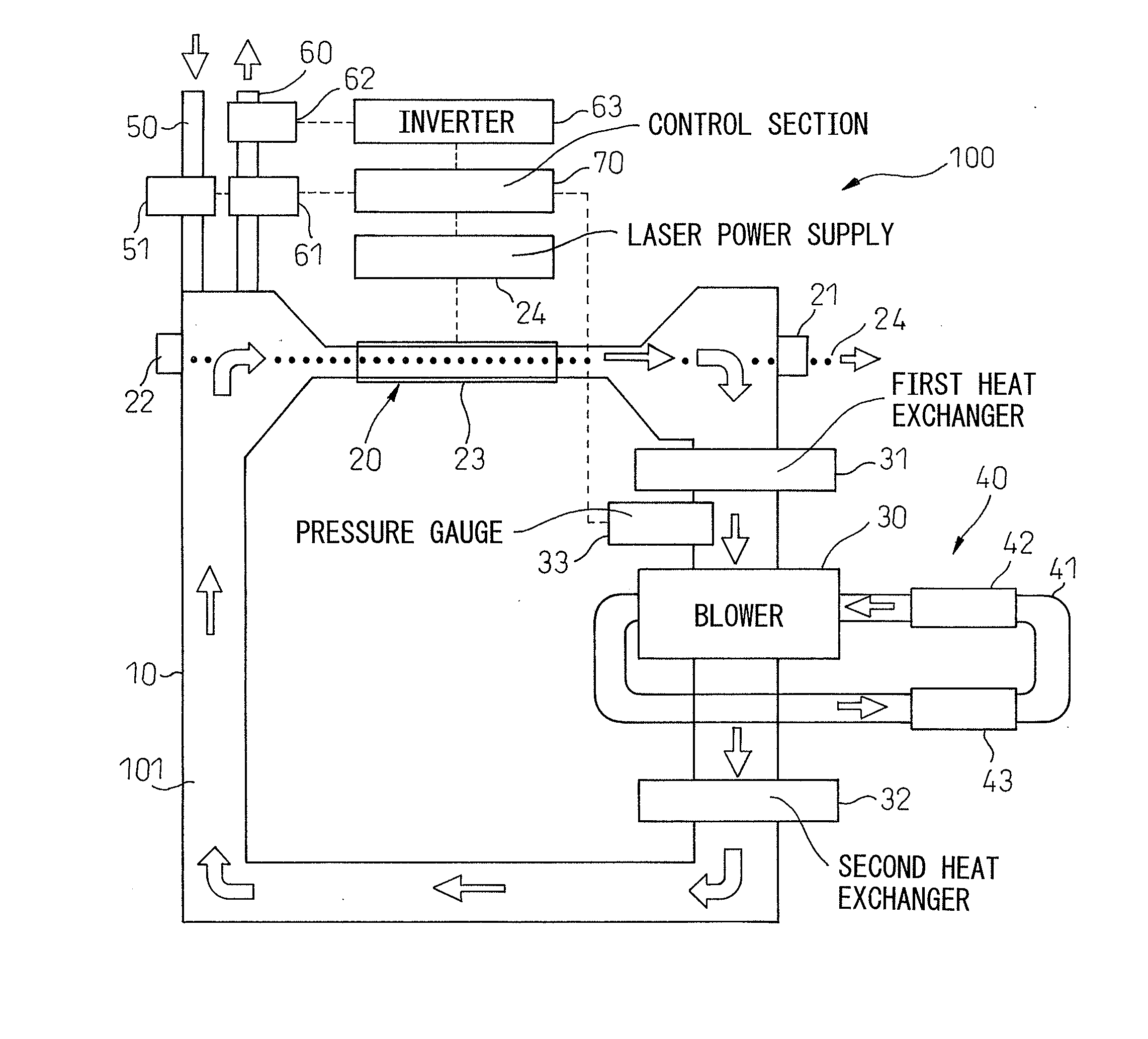
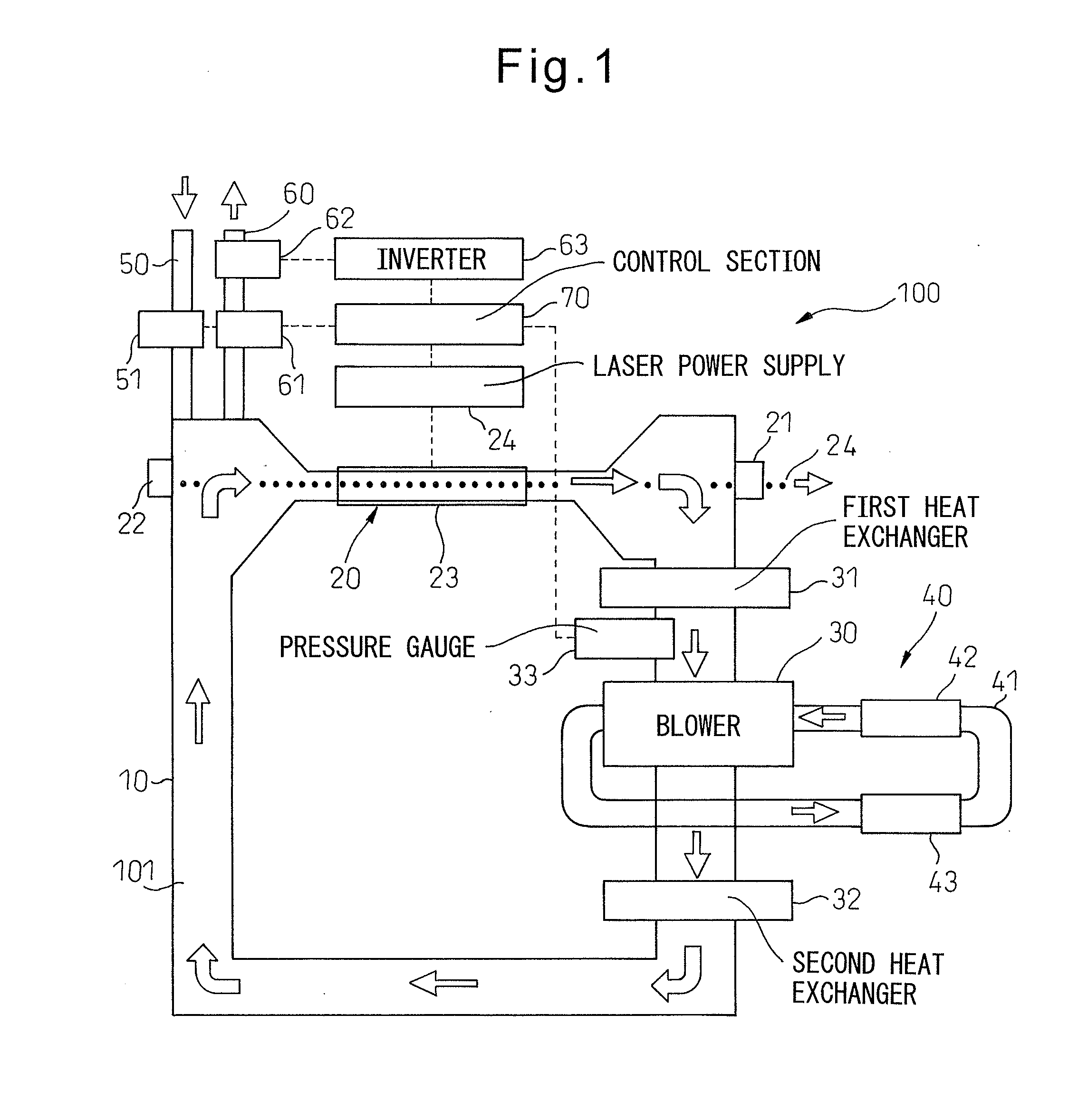
[0016]Hereinafter, referring to FIGS. 1 to 6B, embodiments of the present invention will be described. FIG. 1 is a diagram schematically illustrating a configuration of a gas laser device 100 according to an embodiment of the present invention. This gas laser device 100 comprises a laser gas vessel 10 forming a gas passage 101 through which a laser gas circulates, and a laser oscillator 20 and a blower 30 disposed on gas passage 101. Gas laser device 100 according to this embodiment can be used in many fields such as manufacturing, medical care and measurement.

[0017]Laser gas vessel 10 accommodates a predetermined laser gas isolated from the atmosphere. As the laser gas, a gas medium for laser oscillation including laser media, such as carbon dioxide, nitrogen gas and argon gas, is used.

[0018]Laser oscillator 20 has an output mirror 21, a rear mirror 22, and a discharge tube 23 disposed between output mirror 21 and rear mirror 22. Discharge tube 23 communicates with gas passage 101....


PUM


Abstract

A gas laser device including a blower circulating a laser gas along a gas passage; a pressure detection section detecting a gas pressure of the laser gas in the gas passage; a gas supply and exhaust section supplying the laser gas to the gas passage and exhausting the laser gas from the gas passage; an instruction section instructing a temporary stop of a laser oscillation by a laser oscillator; and a control section controlling the blower and the gas supply and exhaust section in response to an instruction from the instruction section. The control section, once the instruction section instructs the temporary stop, controls the blower to reduce the rotation of the blower or stop the rotation of the blower and controls the gas supply and exhaust section so that the gas pressure detected is a second target gas pressure corresponding to a first target gas pressure during the rotation of the blower.

Description

BACKGROUND OF THE INVENTION[0001]1. Field of the Invention[0002]The present invention relates to a gas laser device that uses a gas as an excitation medium.[0003]2. Description of the Related Art[0004]There is known a gas laser device in which a laser gas vessel is filled with a laser gas as an excitation medium, which is circulated by a blower, and the laser gas is excited by being discharged from discharge electrodes to output laser light. In the device described in Japanese Unexamined Patent Publication (kokai) No. H11-112064 (JP11-112064A), when the device is in a laser ON state in which the laser light is output, the blower is rotated and, when the device is not in the laser ON state, the blower is temporarily stopped.[0005]However, if the blower is temporarily stopped when the device is not in the laser ON state as the device described in JP11-112064A, gas pressure in the laser gas vessel may be changed due to leakage of the vessel and the like. Then, if the temporary stop is ...

Claims


Application Information

Patent Timeline
Patent Type & Authority Applications(United States)
IPC IPC(8): H01S3/036
CPCH01S3/036H01S3/09702H01S3/104
Inventor MURAKAMI, TAKAFUMINISHIO, AKIHIKO
Owner FANUC LTD
Why Eureka
Try Eureka