Image processing device and image processing method

a technology of image processing and image processing device, which is applied in the field of image processing device and image processing method, can solve the problems of reducing the purchasing interest of viewers, troublesome viewing for viewers, and inability to wear glasses at the viewing time, and achieve the effect of low precision of reference-point depth imag

Active Publication Date: 2013-11-28
SONY CORP
View PDF17 Cites 14 Cited by
  • Summary
  • Abstract
  • Description
  • Claims
  • Application Information

AI Technical Summary

Benefits of technology

[0061]According to the first aspect of the present technique, occlusion regions of color images and depth images of viewpoints other than the reference point can be transmitted so that high-quality color images and depth images of the viewpoints other than the reference point can be generated on the receiving end, even if the precision of the reference-point depth image is low.
[0062]According to the second aspect of the present technique, high-quality color images and depth images of viewpoints other than the reference point can be generated even if the precision of the reference-point depth image is low when the occlusion regions of color images and depth images of the viewpoints other than the reference point are transmitted.

Problems solved by technology

However, with such a glasses-involving technique, a viewer needs to purchase glasses as well as a 3D image display device, and this reduces the viewer's purchasing interest.
Also, the need to wear glasses at the time of viewing is troublesome for a viewer.
At present, however, there exist only decoding devices that are capable of decoding color images of two viewpoints.
Therefore, it is difficult to encode, transmit, and decode multi-view color images and depth images as a baseband, and it is necessary to reduce the baseband data amount.

Method used


Image

  • Image processing device and image processing method
  • Image processing device and image processing method
  • Image processing device and image processing method

Examples


first embodiment

Example Structure of an Embodiment of an Image Processing System

[0099]FIG. 5 is a block diagram showing an example structure of an embodiment of an image processing system that includes a transmission device and a reception device as image processing devices to which the present technique is applied.

[0100]In the structure illustrated in FIG. 5, the same components as those in FIG. 1 are denoted by the same reference numerals as those in FIG. 1. The explanations that have already been made will not be repeated.

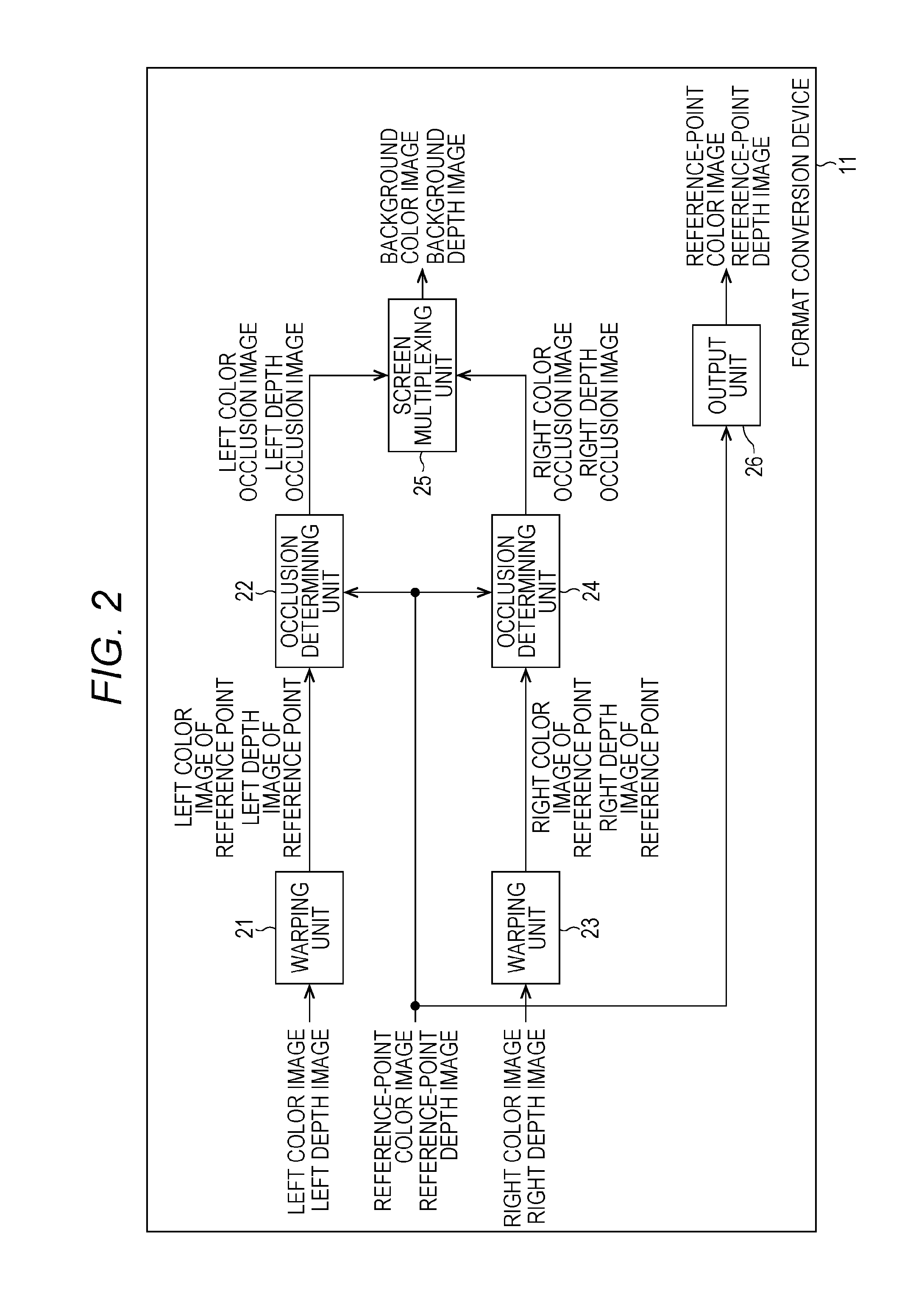
[0101]The structure of the image processing system 50 shown in FIG. 5 differs from the structure shown in FIG. 1, mainly in that the format conversion device 11 is replaced with a format conversion device 51, and the inverse format conversion device 14 is replaced with an inverse format conversion device 52. In the image processing system 50, the format conversion device 51 detects a left-viewpoint occlusion region and a right-viewpoint occlusion region that appear at the inver...

example layout

[Example Layout of the Right / Left Specifying Information]

[0151]FIG. 10 is a diagram showing the pixels corresponding to the values of the respective components of a background depth image.

[0152]In the example shown in FIG. 10, the background depth image is an image formed with 4×4 pixels of so-called YCbCr420. In FIG. 10, circles, squares, and triangles represent the pixels corresponding to the luminance component (the Y component), the Cb component of the chroma component, and the Cr component of the chroma component, respectively.

[0153]As shown in FIG. 10, the Y component of the background depth image has a value for each pixel, and the Cb component and the Cr component have a value for each 2×2 pixels.

[0154]FIG. 11 is a diagram showing an example of bit strings of values of the Cb component and the Cr component.

[0155]In the example shown in FIG. 11, the number of bits of each value of the Cb component and the Cr component is 8.

[0156]In this case, as shown in FIG. 11, the value of...

first specific example

[First Specific Example Structure of the Inverse Format Conversion Device]

[0178]FIG. 13 is a block diagram showing a first specific example structure of the inverse format conversion device 52 shown in FIG. 5.

[0179]In the structure illustrated in FIG. 13, the same components as those in FIG. 3 are denoted by the same reference numerals as those in FIG. 3. The explanations that have already been made will not be repeated.

[0180]The structure of the inverse format conversion device 52 shown in FIG. 13 differs from the structure shown in FIG. 3, mainly in that the screen combining unit 32, the warping unit 33, and the screen combining unit 34 are replaced with a screen combining unit 123, a warping unit 121, and a screen combining unit 124, and a chroma component converting unit 122 is newly provided.

[0181]The warping unit 121 of the inverse format conversion device 52 functions as the receiving unit, and receives the background color image supplied from the multi-view image decoding de...


PUM


Abstract

The present technique relates to an image processing device and an image processing method that enable generation of high-quality color images and depth images of the viewpoints other than the reference point on the receiving end even if the precision of the reference-point depth image is low when the occlusion regions of color images and depth images of the viewpoints other than the reference point are transmitted. A warping unit performs a foreground-prioritized warping operation toward the left viewpoint on the reference-point depth image. Using the reference-point depth image of the left viewpoint obtained as a result of the warping operation, an occlusion determining unit detects a left-viewpoint occlusion region that appears when a viewpoint is converted from the reference point to the left viewpoint. The present technique can be applied to 3D image processing devices, for example.

Description

TECHNICAL FIELD[0001]The present technique relates to image processing devices and image processing methods, and more particularly, to an image processing device and an image processing method that enable generation of high-quality color images and depth images of the viewpoints other than the reference point on the receiving end even if the precision of the reference-point depth image is low when the occlusion regions of color images and depth images of the viewpoints other than the reference point are transmitted.BACKGROUND ART[0002]In recent years, attention is being paid to 3D images. As a popular technique for viewing such 3D images, there is currently a technique by which a viewer views images of two viewpoints that are alternately displayed. In viewing the images of two viewpoints, the viewer wears glasses that open the shutter for the left eye when one of the images of two viewpoints is displayed, and open the shutter for the right eye when the other one of the images is dis...

Claims


Application Information

Patent Timeline
Patent Type & Authority Applications(United States)
IPC IPC(8): G06K9/00
CPCG06K9/00201G06T15/205H04N2213/005H04N13/111G06V20/64
Inventor TAKAHASHI, YOSHITOMO
Owner SONY CORP
Why Eureka
Try Eureka