Software defined networking photonic routing systems and methods

a software-defined networking and photonic routing technology, applied in the field of optical network systems and methods, can solve the problems of impairment effects, signal loss, etc., and the routing considerations of individual optical channels can be extremely complex, and the routing considerations of individual optical channels are becoming less applicabl

Active Publication Date: 2013-11-28
CIENA
View PDF4 Cites 62 Cited by
  • Summary
  • Abstract
  • Description
  • Claims
  • Application Information

AI Technical Summary

Benefits of technology

[0008]In yet another exemplary embodiment, a photonic network includes a plurality of nodes each supporting add and drop of at least Y wavelengths; a plurality of optical links interconnecting the plurality of nodes, wherein the plurality of optical links support up to X wavelengths, Y≦X an optical routing protocol configured to compute a loop-free path through the plurality of nodes on the plurality of links, wherein the loop-free path is computed for one of the X wavelengths or a group of the X wavelengths using routing constructs adapted to a photonic domain; and optical components at each of the plurality of nodes configured to selectively block at least one of the X wavelengths based on the computed loop-free path. The loop-free path can be computed through a spanning tree computation. The spanning tree computation can utilize costs of the plurality of optical links set to bias selection of amplified links over unamplified links. The plurality of nodes can include a broadcast and select architecture. The loop-free path can be computed through a Shortest Path Bridging computation. The Shortest Path Bridging computation can be compliant to IEEE 802.1aq (2011) and replace Ethernet bridges with the plurality of nodes and Ethernet links with the plurality of links; and wherein the Shortest Path Bridging computation defines a Shortest Path Virtual Local Area Network Identifier (SPVID) in the photonic network as identifying unidirectional Shortest Path Trees for multicast traffic for one or more wavelengths sharing common root and endpoints.
[0009]Wavelength selective switches in the broadcast and select architecture can be programmed to block at least one wavelength on ports not on a Shortest Path Tree for wavelengths belonging to that Shortest Path Tree. Responsive to a failed link of the plurality of links, the optical routing protocol can be configured to compute an updated loop-free path through the plurality of nodes on the plurality of links with the failed link excluded from the computation. The optical components at each of the plurality of nodes can be reconfigured to selectively block and unblock the at least one of the X wavelengths based on the updated loop-free path. The loop-free path can be comput

Problems solved by technology

As such, routing of individual optical channels can be an extremely complex proposition.
As technology evolves, impairment effects, signal loss, etc. are becoming le

Method used


Image

  • Software defined networking photonic routing systems and methods
  • Software defined networking photonic routing systems and methods
  • Software defined networking photonic routing systems and methods

Examples


Embodiment Construction

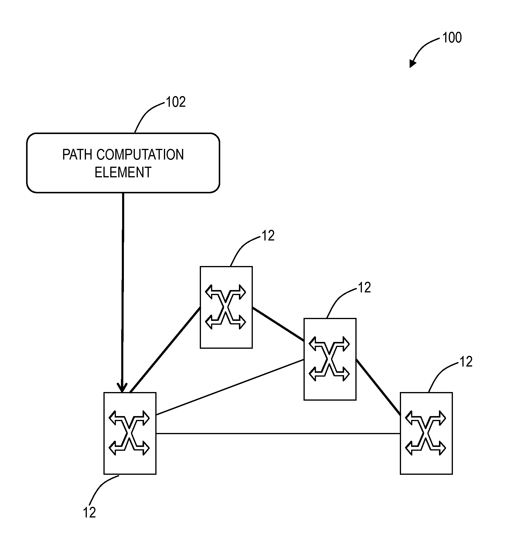
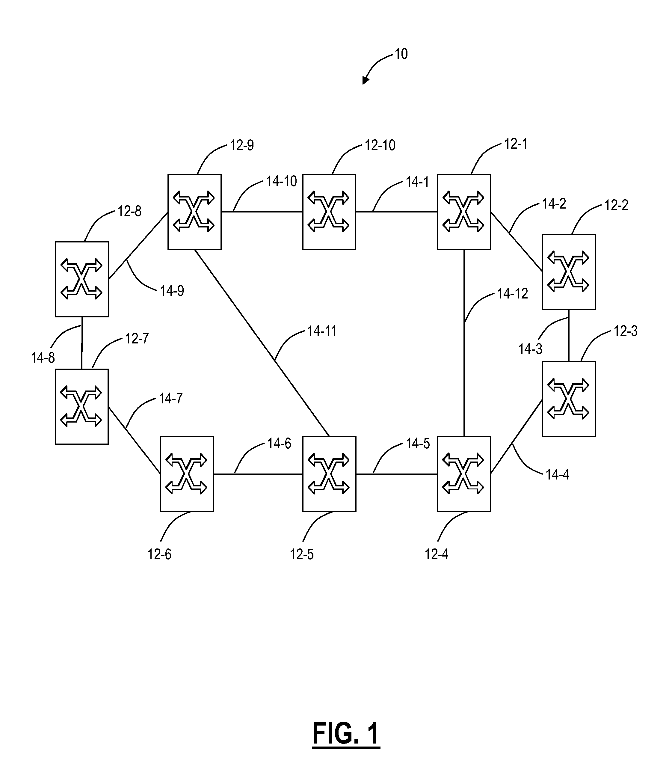
[0024]In various exemplary embodiments, routing systems and methods in optical networks such as, for example, broadcast and select optical networks, all-broadcast optical networks, etc., are described which use loop avoidance techniques to find loop-free paths through the network for one or more wavelengths. Using the routing systems and methods, wavelengths or groups of wavelengths are routed in a single path a network. This single path can be determined by computing a loop free forwarding path through the network. In particular, the routing systems and methods can utilize various Layer 2 and Layer 3 constructs in the photonic domain to quickly and efficient compute loop free paths on a per wavelength or per group of wavelength basis through networks. These loop free paths can be computed in response to failures thereby providing a quick and efficient restoration mechanism in the photonic domain. Stated differently, the routing systems and methods approach routing / path selection in...


PUM


Abstract

A network includes a plurality of interconnected nodes utilizing an all-broadcast architecture for a plurality of wavelengths therebetween; a routing protocol configured to compute a loop-free path through the plurality of interconnected nodes, wherein the loop-free path is computed for at least one wavelength of the plurality of wavelengths using routing constructs adapted to a photonic domain; and at least one blocking element configured to selectively block the at least one wavelength based on the computed loop-free path. A routing method photonic node are also disclosed.

Description

CROSS-REFERENCE TO RELATED APPLICATION(S)[0001]The present non-provisional patent application / patent is a continuation-in-part of U.S. patent application Ser. No. 13 / 452,322, filed on Apr. 20, 2012, and entitled “PHOTONIC ROUTING SYSTEMS AND METHODS FOR LOOP AVOIDANCE,” and a continuation-in-part of U.S. patent application Ser. No. 13 / 371,920, filed on Feb. 13, 2012, and entitled “COLORLESS, DIRECTIONLESS, AND GRIDLESS OPTICAL NETWORK, NODE, AND METHOD,” the contents of each are incorporated in full by reference herein.FIELD OF THE INVENTION[0002]Generally, the field of art of the present disclosure pertains to optical network systems and methods, and more particularly, to software defined networking (SDN) photonic routing systems and methods in optical networks such as, for example, broadcast and select optical networks, all-broadcast optical networks, etc., which use loop avoidance techniques to find loop-free paths through the network for one or more wavelengths.BACKGROUND OF THE...

Claims


Application Information

Patent Timeline
IPC IPC(8): H04J14/02H04L45/18H04L45/28
CPCH04J14/02H04J14/0204H04J14/0206H04J14/0212H04J14/0213H04J14/022H04J14/0238H04J14/0267H04J14/0268H04J14/0275H04J14/0286H04J14/0297H04Q11/0005H04Q2011/0015H04Q2011/0016H04Q2011/0018H04L45/62H04L45/64H04L45/18H04L45/28H04J14/0227H04L41/122H04L45/12H04B10/27H04L41/12H04Q11/0062H04Q2011/009
Inventor BOERTJES, DAVID WELDONSHEW, STEPHEN DANIEL
Owner CIENA
Why Eureka
Try Eureka