
Aircraft propulsion system and a method of controlling the same

a technology of propulsion system and airframe, which is applied in the direction of liquid fuel engines, instruments, machines/engines, etc., can solve the problems of reducing the speed of redirected airflow, limiting the amount of bypass ratio that can be increased, and generating higher noise levels. , to achieve the effect of reducing the velocity of redirected airflow

Active Publication Date: 2013-11-28
ROLLS ROYCE PLC
View PDF2 Cites 16 Cited by
  • Summary
  • Abstract
  • Description
  • Claims
  • Application Information

AI Technical Summary

Benefits of technology

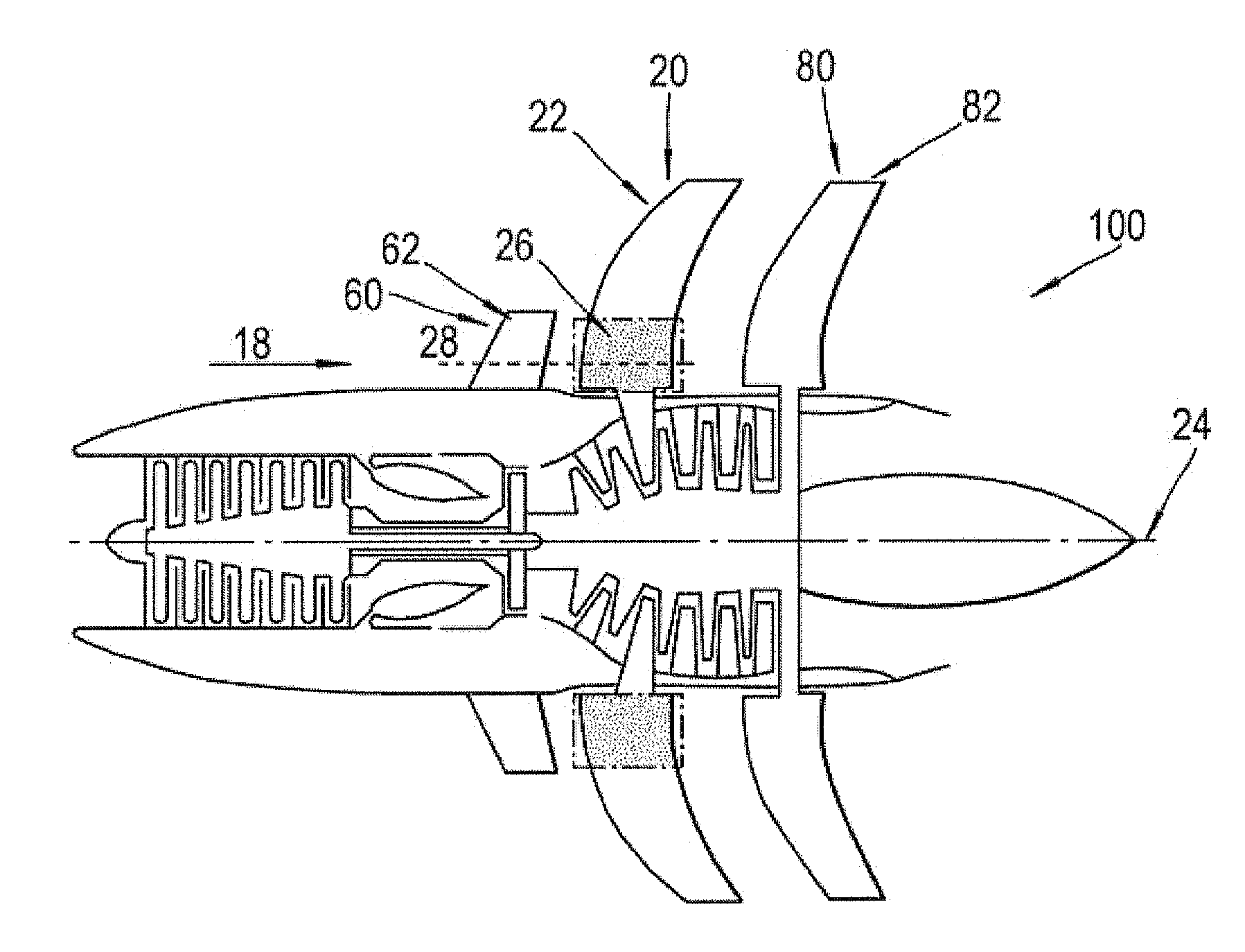
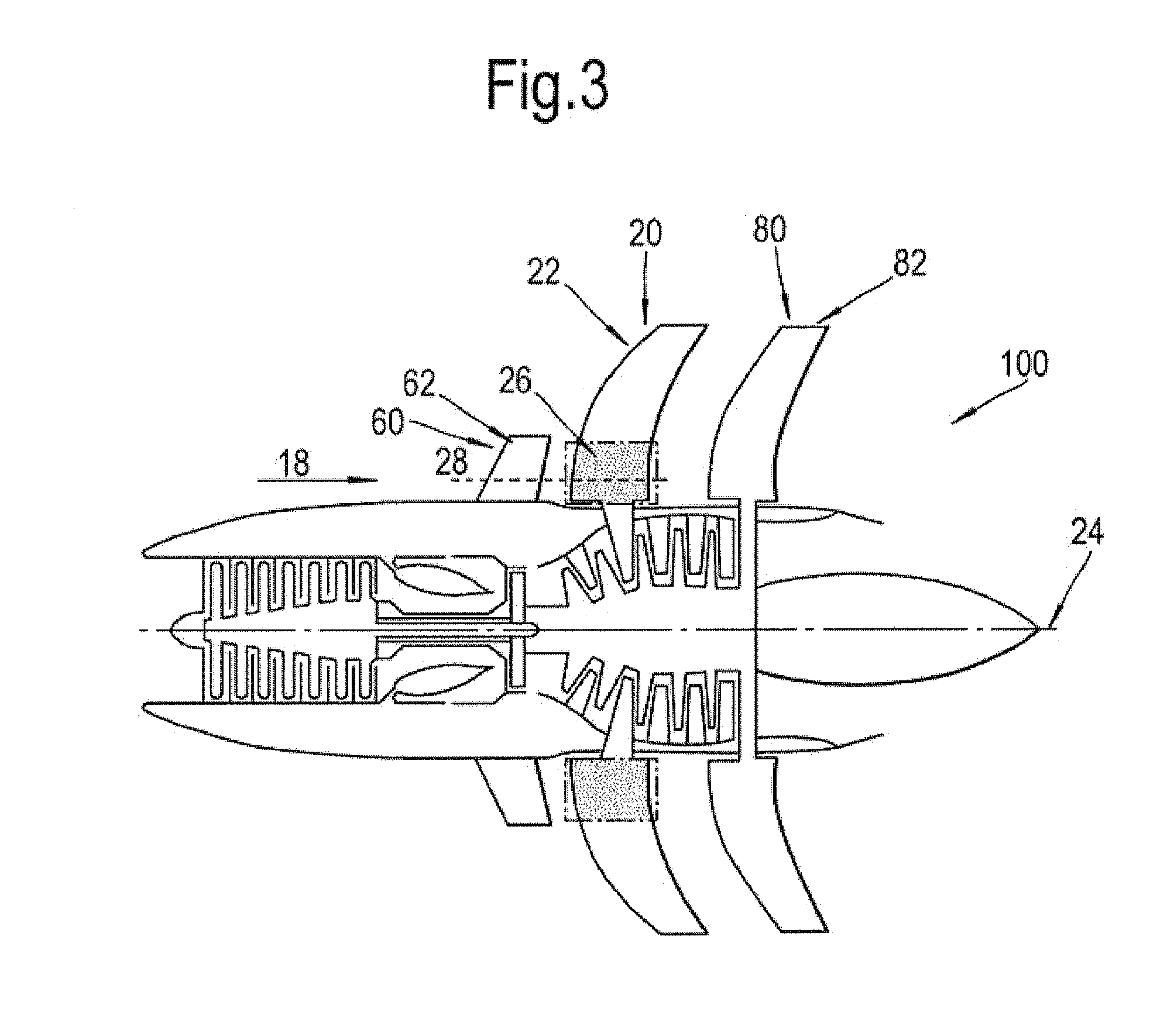
The present invention is an aircraft propulsion system that includes a rotor assembly and a vane assembly. The vane assembly is located between the rotor assembly and is fixed about the axis of rotation. The vane assembly is designed to direct airflow into the rotor assembly in a way that reduces the velocity of the airflow relative to the rotor blades. This helps to improve the efficiency of the system, reduce noise, and increase the number of rotor blades.

Problems solved by technology

However, there is a limit to how much the bypass ratio can be increased as eventually the weight and drag penalties associated with the size of the required engine nacelle outweigh the reduction in fuel consumption.
A problem with open rotor engines is that they generate higher noise levels than conventional turbofan engines, in which noise from the fan is muffled by the nacelle.
This may result in the flow regime through the open rotor suffering from choking.
The high relative inlet Mach numbers and the limitation in throat area driven by the required minimum blade thickness can result in the airflow through the rotor becoming choked.

Method used


Image

  • Aircraft propulsion system and a method of controlling the same
  • Aircraft propulsion system and a method of controlling the same
  • Aircraft propulsion system and a method of controlling the same

Examples


Embodiment Construction

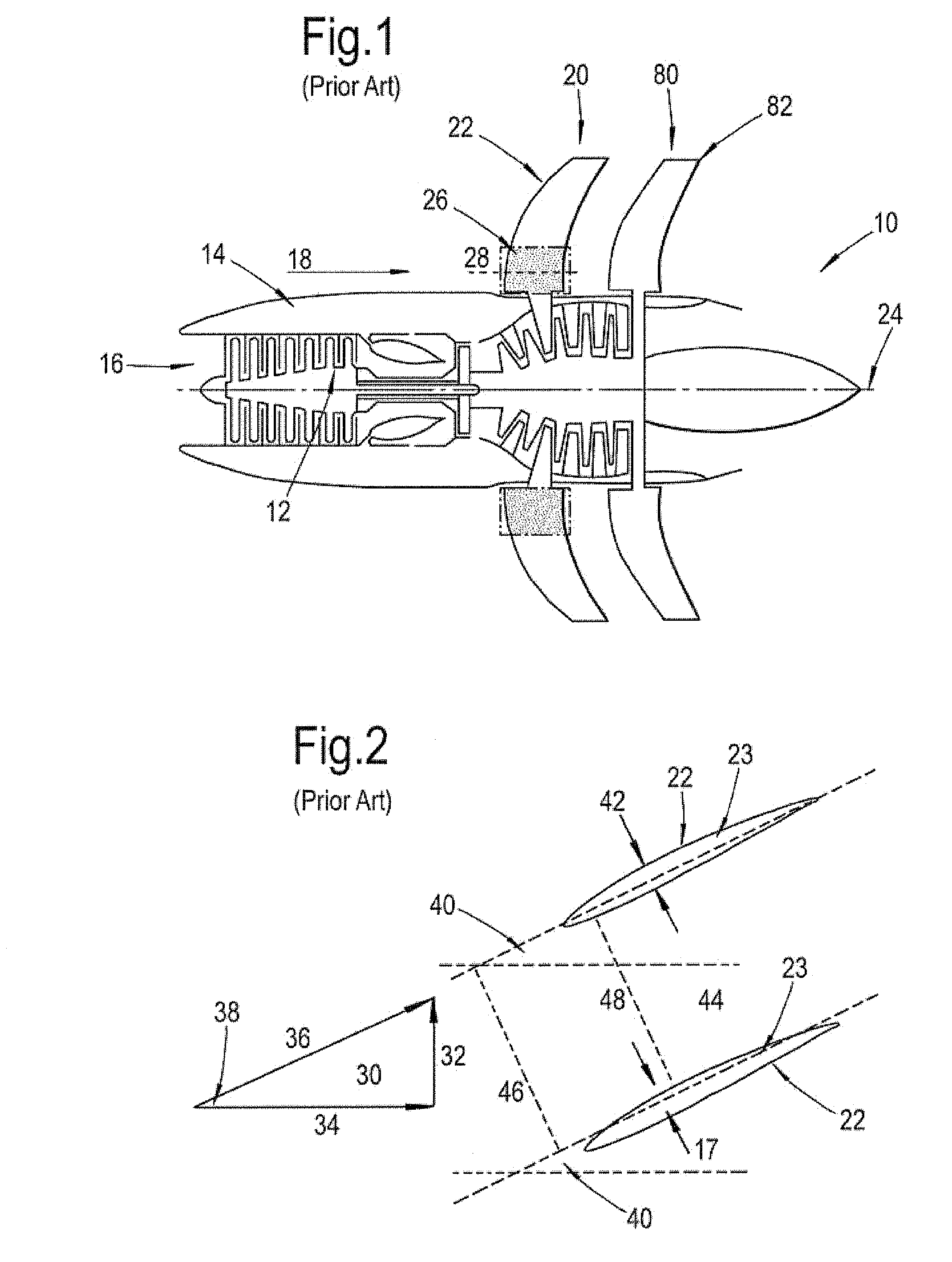
[0066]Referring to FIG. 1, a conventional open-rotor turbofan engine assembly is designated generally by the reference numeral 10.

[0067]The open rotor engine assembly 10 comprises an engine core 12, a nacelle 14 which separates the core airflow 16 from an external airflow 18, a first rotor assembly 20 comprising a plurality of first rotor blades 22, and a second rotor assembly 80 comprising a plurality of second rotor blades 82.

[0068]Both the first and second rotor assemblies 20, 80 rotate about an axis of rotation 24.

[0069]For a given flight condition, the velocity of the external airflow 18 is sufficient to cause a choked region 26 to form over a portion of the span of the first rotor 20, as indicated in FIG. 1.

[0070]FIG. 2 shows, in diagrammatic form, the airflow 18 entering the first rotor assembly 20 of the engine assembly 10. A velocity triangle 30 represents the vector components of the airflow 18 at a given rotor radius 28.

[0071]A rotational velocity vector 32, which represe...


PUM


Abstract

An aircraft propulsion system has a propulsive rotor assembly rotatable about an axis of rotation and comprising a plurality of blades and a rotationally fixed vane assembly located adjacent to the propulsive rotor assembly and arranged circumferentially around the axis of rotation. As airflow enters the propulsive rotor assembly, a portion of the airflow passes over the vane assembly which is configured to direct the airflow away from the rotor blades so as to reduce the relative velocity of the redirected airflow over the rotor blades. This results in a reduced tendency of the airflow through the propulsive rotor assembly to become choked.

Description

[0001]This invention claims the benefit of UK Patent Application No. 1114380.7, filed on 22 Aug. 2011, which is hereby incorporated herein in its entirety.FIELD OF THE INVENTION [0002]This invention relates to aircraft propulsion systems and particularly, but not exclusively, to aircraft propulsion systems which utilise propfan or unducted fan type engines generally characterised by two contra-rotating propellers or open rotors.BACKGROUND TO THE INVENTION [0003]It is known that increasing the bypass ratio of a conventional turbofan engine can reduce its fuel consumption and consequent level of CO2 emissions. This characteristic has been exploited by engine manufacturers by progressively increasing the bypass ratios of modern turbofan engines.[0004]However, there is a limit to how much the bypass ratio can be increased as eventually the weight and drag penalties associated with the size of the required engine nacelle outweigh the reduction in fuel consumption.[0005]An alternative to ...

Claims


Application Information

Patent Timeline
IPC IPC(8): B64C11/00
CPCB64C11/00B64C11/48B64D29/04B64D2027/005Y02T50/60F01D9/041
Inventor NEUTEBOOM, MARTIN O.
Owner ROLLS ROYCE PLC
Learn More