
Force sensor

a technology of force sensor and force sensor, which is applied in the direction of instruments, string rackets, force/torque/work measurement apparatus, etc., can solve the problems of inability to make thin sensors in their entirety, inability to make mechanical structures thick,

Inactive Publication Date: 2013-12-05
TRI FORCE MANAGEMENT CORP
View PDF4 Cites 33 Cited by
  • Summary
  • Abstract
  • Description
  • Claims
  • Application Information

AI Technical Summary

Benefits of technology

The patent text describes how to set the clearance in a way that prevents a force receiving substrate or ring from being displaced when a certain level of force or moment is applied. This is accomplished by bringing the lower end of the substrate or the displacement control screw into contact with the outer or inner surface of the supporting substrate or ring. The technical effect is that it ensures the stability and accuracy of the force receiving mechanism.

Problems solved by technology

However, in any of the multi-axis force sensors disclosed in the above-described Patent Documents, a mechanical structure is inevitably made thick.
Therefore, it is difficult to make thin the sensor in its entirety.

Method used


Image

  • Force sensor
  • Force sensor
  • Force sensor

Examples


Embodiment Construction

[0232]Hereinafter, the present invention will be described based on illustrated embodiments.

>>

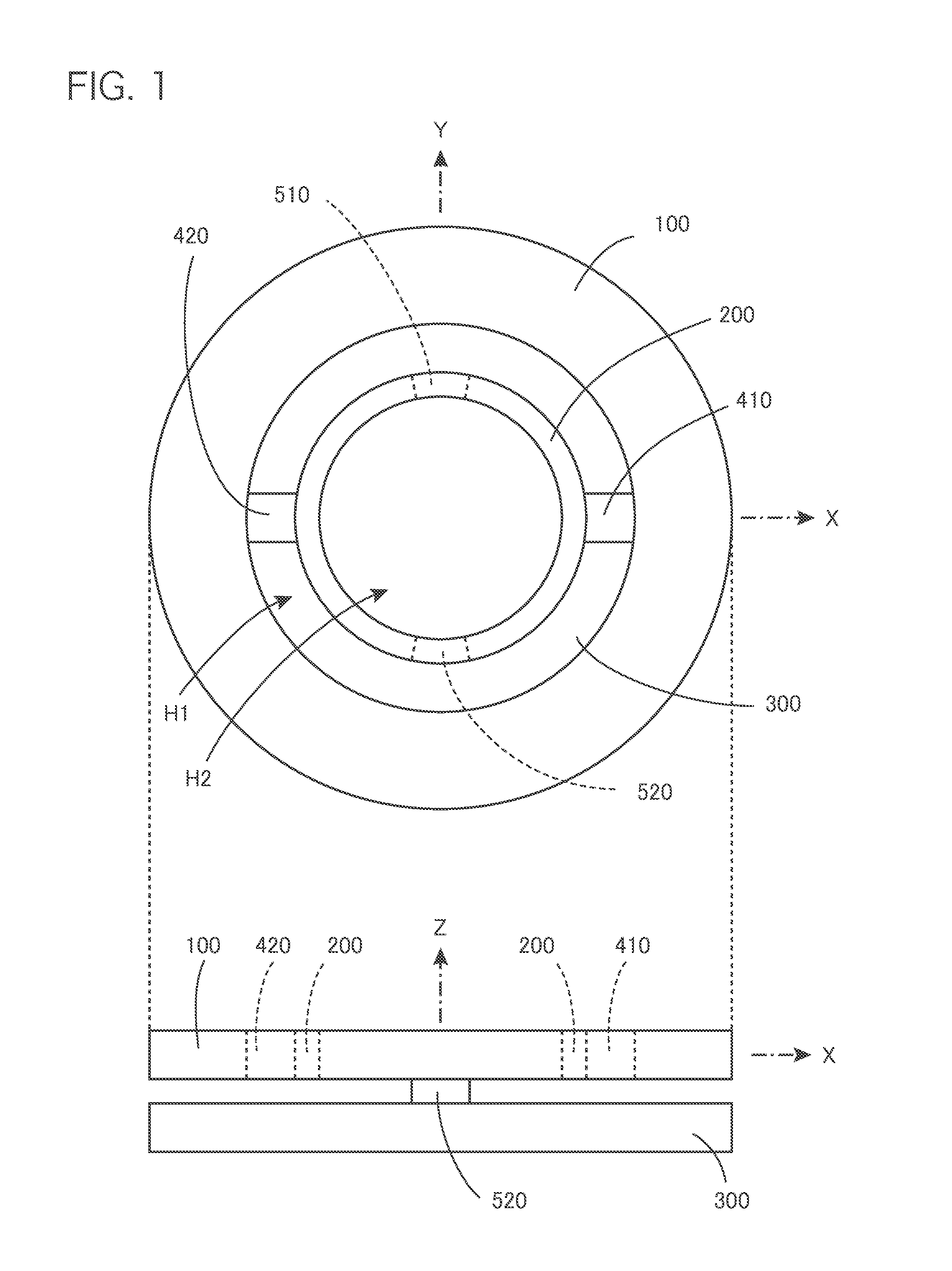
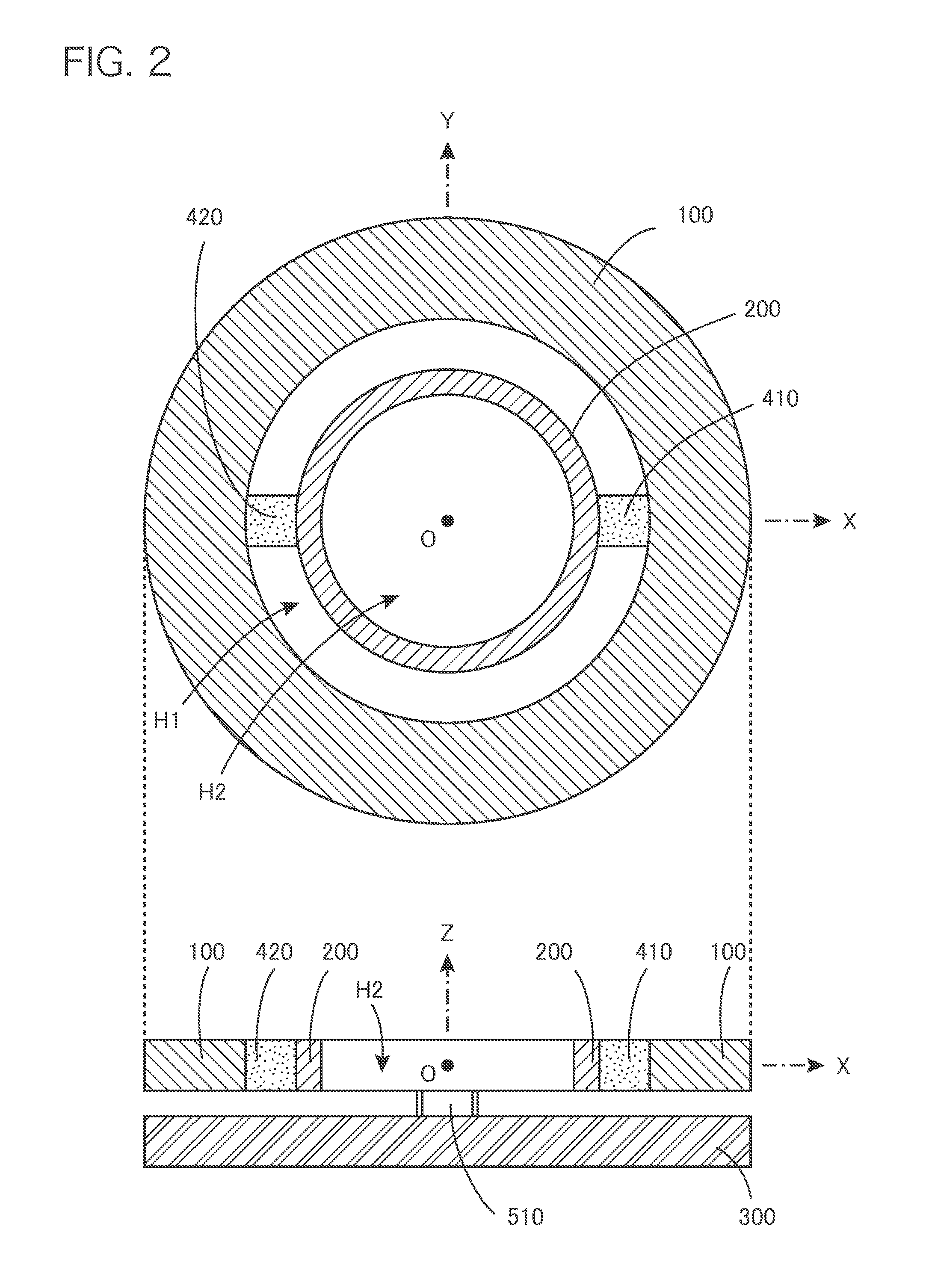
[0233]First, a description will be given about a constitution of a basic structure of a force sensor according to the present invention and a principle of detecting force and moment by utilizing the basic structure. A force sensor according to the present invention has functions to detect force or moment at least on one axis among force in the direction of each coordinate axis and moment around each coordinate axis in an XYZ three-dimensional orthogonal coordinate system. Therefore, hereinafter, a description will be given of a constitution of the basic structure of the force sensor which is arranged in the XYZ three-dimensional orthogonal coordinate system.

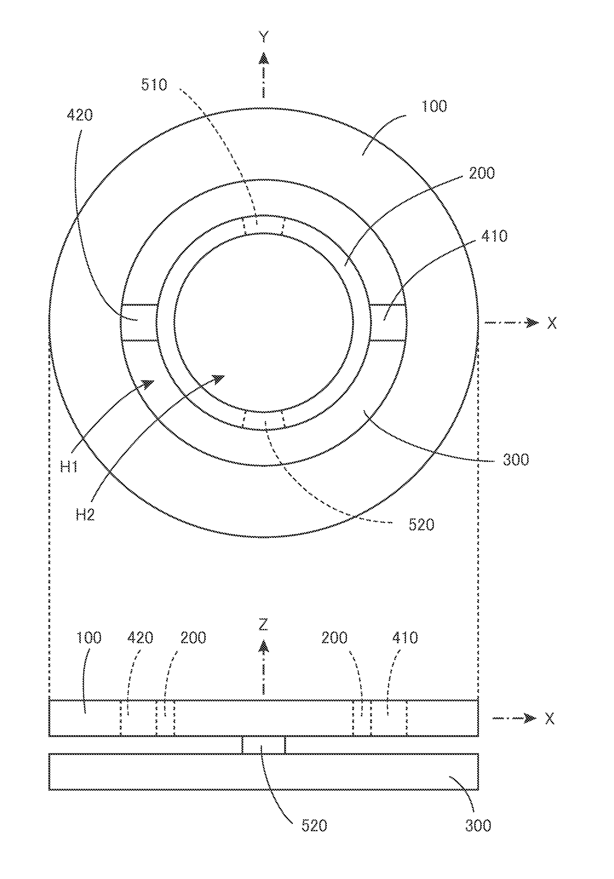
[0234]FIG. 1 is a top view (the upper part of the figure) and a side view (the lower part of the figure) for showing the basic structure of the force sensor according to a basic embodiment of the present invention. In the top view, the X...


PUM

PropertyMeasurementUnit
forceaaaaaaaaaa
elastic deformationaaaaaaaaaa
thicknessaaaaaaaaaa

Abstract

With the Z-axis given as a central axis, on an XY-plane, arranged are a rigid force receiving ring, a flexible detection ring inside thereof, and a cylindrical fixed assistant body further inside thereof. Two fixing points on the detection ring are fixed to a supporting substrate, and two exertion points are connected to the force receiving ring via connection members. When force and moment are exerted on the force receiving ring, with the supporting substrate fixed, the detection ring undergoes elastic deformation. Capacitance elements or others are used to measure distances between measurement points and the fixed assistant body and distances between the measurement points and the supporting substrate. Elastic deformation of the detection ring is recognized for mode and magnitude, thereby detecting a direction and magnitude of force or moment which is exerted.

Description

TECHNICAL FIELD[0001]The present invention relates to a force sensor and in particular to a thin-type force sensor which is suitable for detecting force in the direction of each coordinate axis and moment around each coordinate axis in a three-dimensional orthogonal coordinate system.BACKGROUND ART[0002]Various types of force sensors have been used to control motions of robots and industrial machines. Also, a downsized force sensor has been incorporated as a man-machine interface of an input device for electronics. In order to reduce dimensions and cost, a force sensor to be used in the above-described applications is required to be simple in structure as much as possible and also to independently detect force for each coordinate axis in a three dimensional space.[0003]At present, generally-used multi-axis force sensors are categorized into such a type that a specific directional component of force exerted on a mechanical structure is detected as displacement occurring at a specific...

Claims


Application Information

Patent Timeline
Patent Type & Authority Applications(United States)
IPC IPC(8): G01L5/16
CPCG01L5/165G01L1/14G01L1/2206G01L3/1442G01L3/1457G01L5/0076G01L5/1627
Inventor OKADA, KAZUHIRONISHIOKI, NOBUHISA
Owner TRI FORCE MANAGEMENT CORP
Learn More