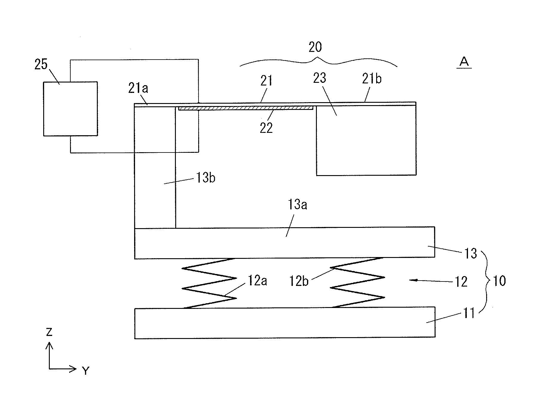
Piezoelectric power generator
a power generator and piezoelectric technology, applied in piezoelectric/electrostrictive/magnetostrictive devices, piezoelectric/electrostriction/magnetostriction machines, electrical equipment, etc., can solve the problems of increasing the amount of power generation, increasing the bending stress applied to the generating device, etc., to achieve good linearity, improve the bending vibration of the generating device, and improve the effect of generating device bending and vibrating
- Summary
- Abstract
- Description
- Claims
- Application Information
AI Technical Summary
Benefits of technology
Problems solved by technology
Method used
Image
Examples
second embodiment
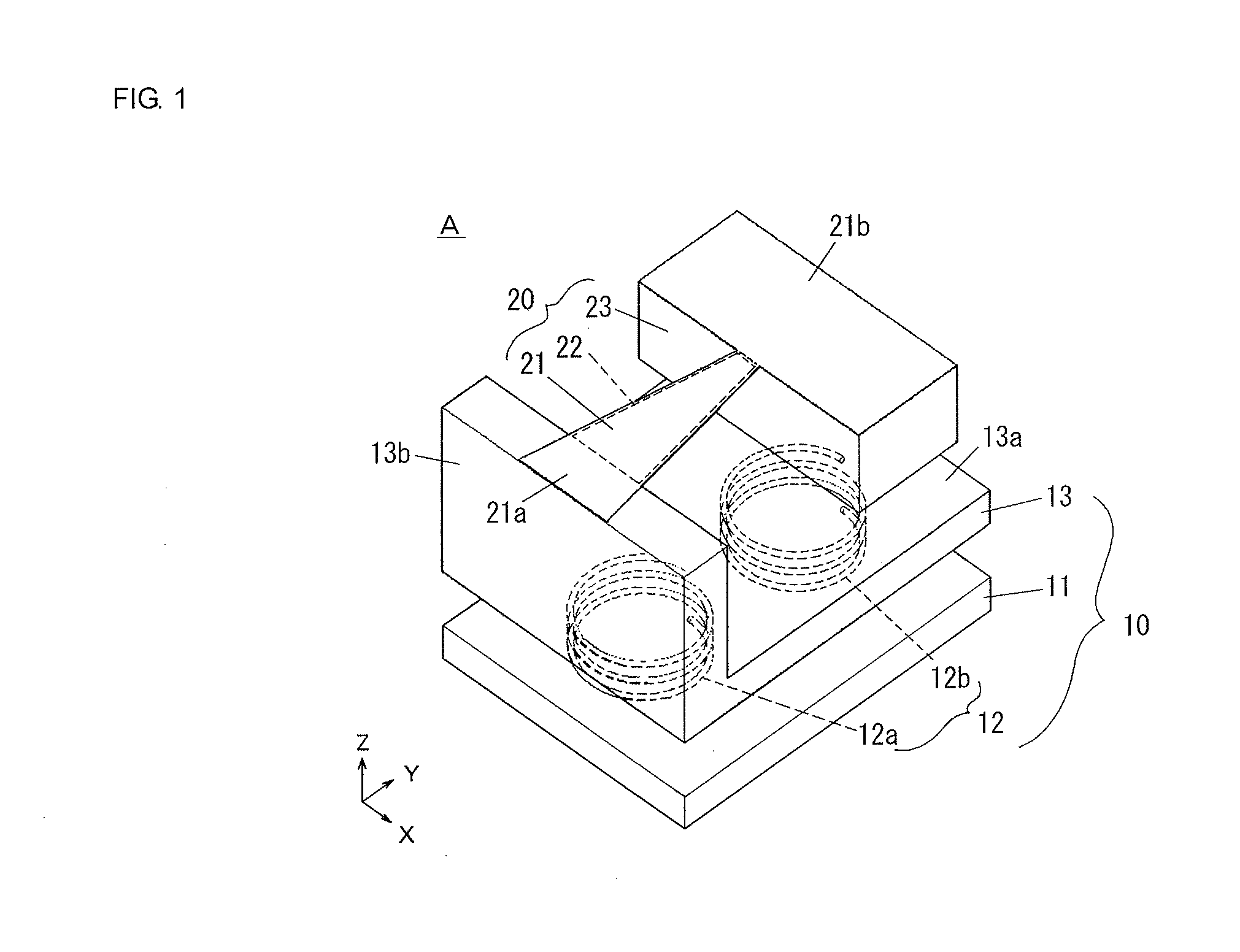
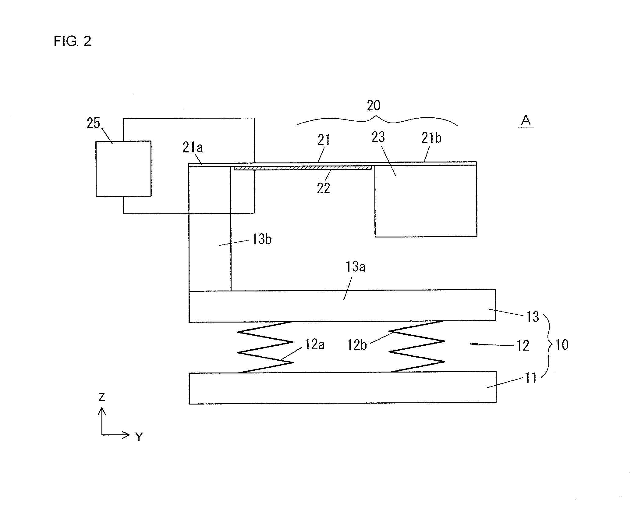
[0053]FIG. 9 illustrates a second embodiment of the piezoelectric power generator according to the present invention. A piezoelectric power generator B of the present embodiment uses four coil springs 12c to 12f as the spring means 12. The coil springs 12c to 12f are spaced in the X-direction on both sides of the generating device 20, and are also spaced in the Y-direction. The piezoelectric power generator B of the present embodiment is the same as the piezoelectric power generator A of the first embodiment, except for the configuration of the spring means 12.
[0054]Using the four coil springs 12c to 12f as the spring means 12 in the present embodiment stabilizes the position of the swing axis CS of the first weight member 13, and reduces movement in the right-and-left direction (i.e., swing about the Y-axis). It is thus possible to efficiently convert an external vibration to a swing of the first weight member 13, further amplify the amount of displacement of the generating device ...
third embodiment
[0055]FIG. 10 illustrates a third embodiment of the piezoelectric power generator according to the present invention. A piezoelectric power generator C of the present embodiment uses four U-shaped leaf springs 12g to 12j as the spring means 12. The arrangement of the leaf springs 12g to 12j is the same as the arrangement of the coil springs 12c to 12f illustrated in FIG. 9. The piezoelectric power generator C of the present embodiment is the same as the piezoelectric power generator A of the first embodiment, except for the configuration of the spring means 12. The effects of the present embodiment are the same as those of the second embodiment. Using the leaf springs, instead of the coil springs, as the spring means 12 facilitates attachment of the spring means 12 to the base member 11 and the first weight member 13. Note that the leaf springs do not necessarily need to be U-shaped, and the number of the leaf springs does not necessarily need to be four.
fourth embodiment
[0056]FIG. 11 illustrates a generating device used in a fourth embodiment of the piezoelectric power generator according to the present invention. A piezoelectric power generator D of the present embodiment uses a generating device 30 as the generating device. The generating device 30 of the present embodiment includes a vibrating plate 31 such as a metal plate, piezoelectric elements 32a to 32c bonded to both principal surfaces of the vibrating plate 31, and a second weight member 33 for excitation. Note that the piezoelectric elements 32a to 32c are omitted in FIG. 11(a). The piezoelectric power generator D of the present embodiment is the same as the piezoelectric power generator A of the first embodiment, except for the configuration of the generating device 30.
[0057]A fixed portion 31d, which is one end of the vibrating plate 31, is secured to the upper surface of the support base portion 13b of the first weight member 13. The other end of the vibrating plate 31 is a free end, ...
PUM
 Abstract
Description
Claims
Application Information
 - R&D
- Intellectual Property
- Life Sciences
- Materials
- Tech Scout
- Unparalleled Data Quality
- Higher Quality Content
- 60% Fewer Hallucinations
Browse by: Latest US Patents, China's latest patents, Technical Efficacy Thesaurus, Application Domain, Technology Topic, Popular Technical Reports.
© 2025 PatSnap. All rights reserved.Legal|Privacy policy|Modern Slavery Act Transparency Statement|Sitemap|About US| Contact US: help@patsnap.com


