
Mounting apparatus for an audio/video system and related methods and systems

Active Publication Date: 2013-12-05
MILLSON CUSTOM SOLUTIONS
View PDF3 Cites 60 Cited by
  • Summary
  • Abstract
  • Description
  • Claims
  • Application Information

AI Technical Summary

Benefits of technology

The invention provides a way to have a large, user-accessible space within a confined space for supporting in-wall components. This is possible because of a removable cover that conceals a peripheral portion of a finished wall opening. The signal processor can support more sophisticated processing, decoding of various formats, and upgrading as new formats and standards are developed.

Problems solved by technology

It is especially difficult to address the above concerns given that consumers have strong but divergent preferences regarding which components should be integrated into their multimedia system and specifically how they are integrated or configured.
Unfortunately, such installations occupy valuable floor space and are often inelegantly bulky.
In-wall multimedia system installations, on the other hand, while saving on floor space and bulk, lack flexibility for accommodating a consumer's component preferences because many commercial off-the-shelf components cannot be easily mounted inside the confined space of a wall, and moreover, in-wall installation of such components may cause heat dissipation problems that can damage the system.
In-wall multimedia system installations further tend to lack upgradability and serviceability due to the typical permanence of in-wall installation and the subsequent lack of access to in-wall system components.
The system may be readily upgradeable in terms of its looks by unsophisticated persons such as interior designers, and in terms of its hardware, by unsophisticated service technician due to the modularity of system components and the plug-and-play simplicity of their interconnection.

Method used


Image

  • Mounting apparatus for an audio/video system and related methods and systems
  • Mounting apparatus for an audio/video system and related methods and systems
  • Mounting apparatus for an audio/video system and related methods and systems

Examples


Embodiment Construction

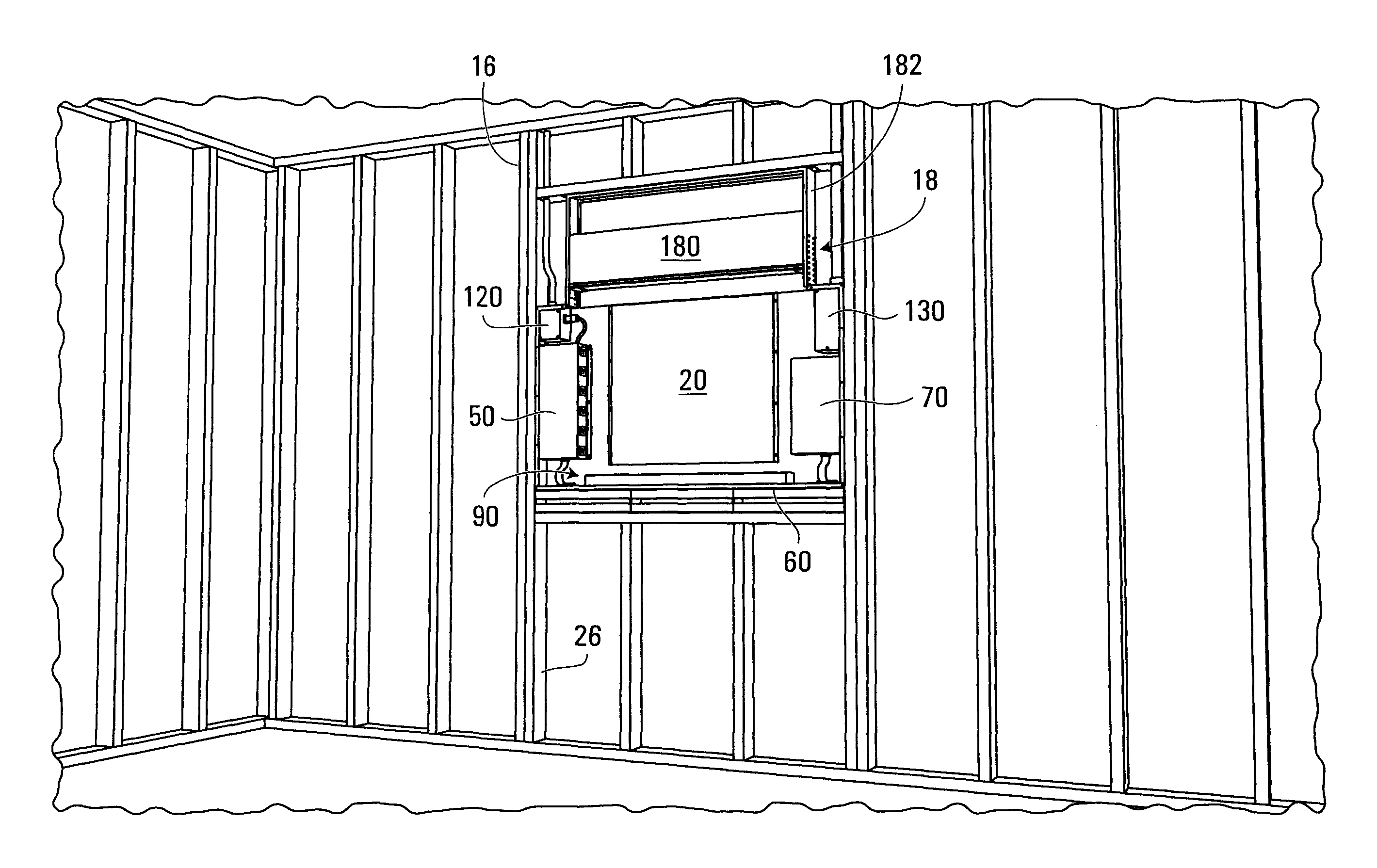
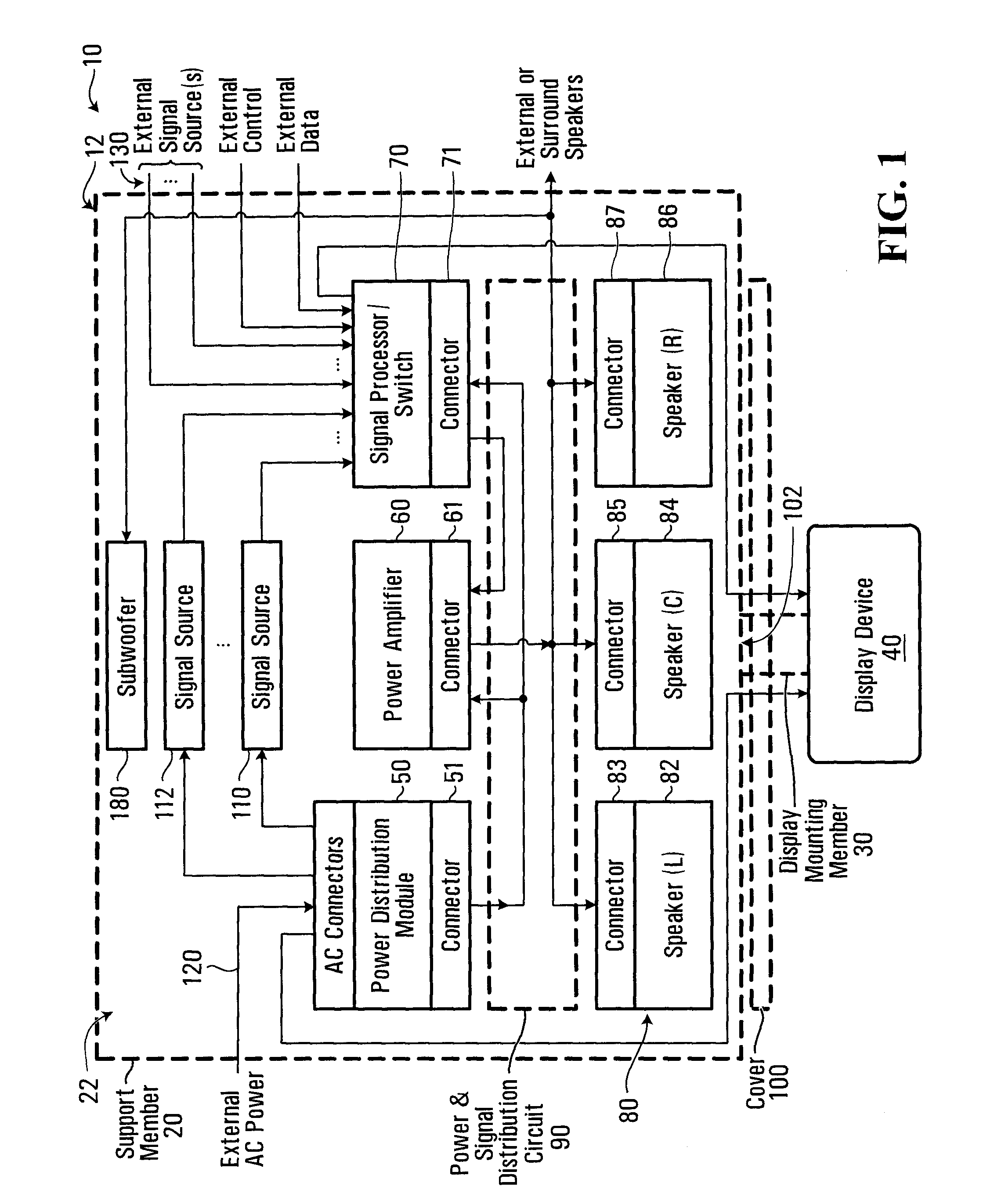
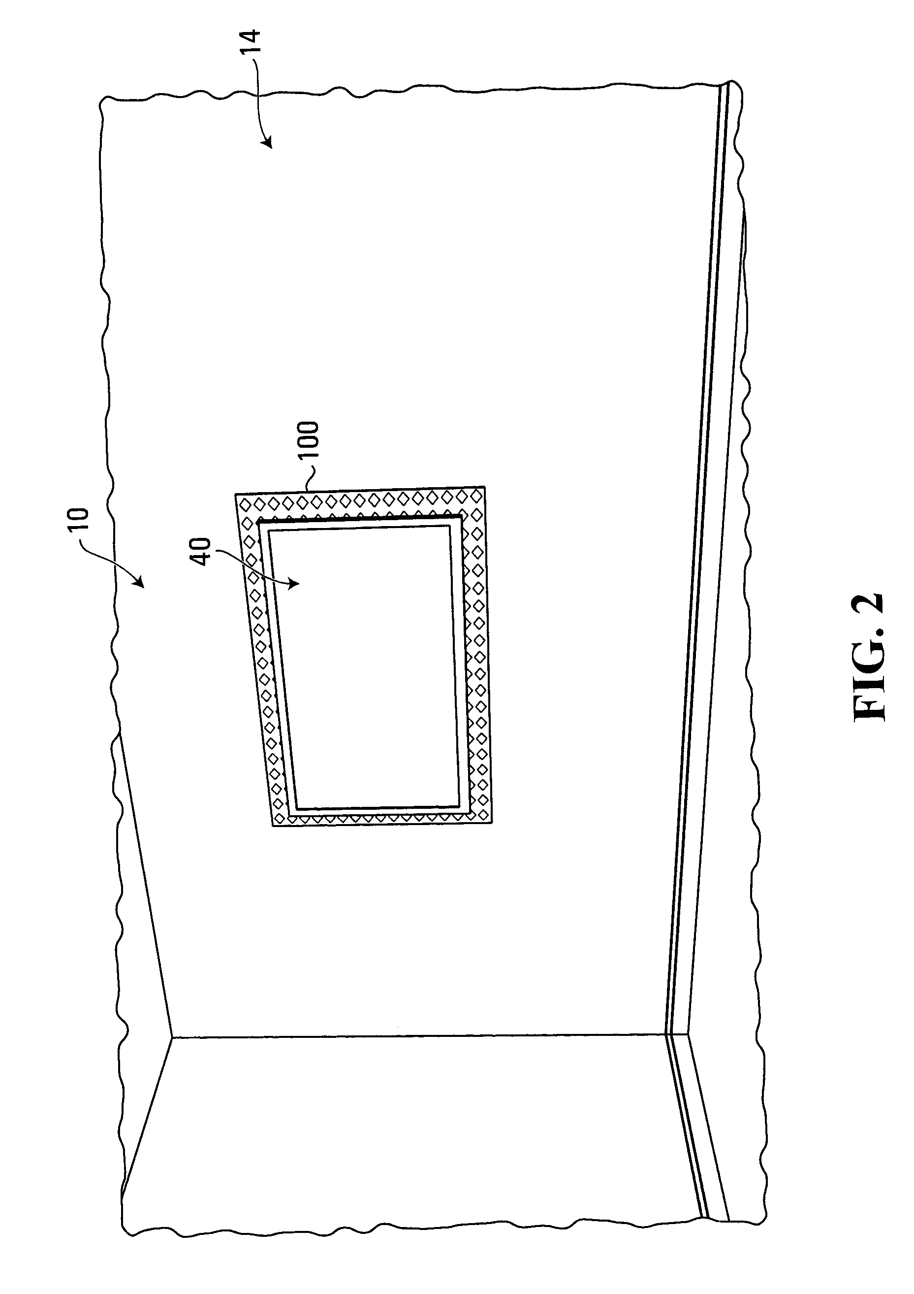
[0069]Referring to FIG. 1, an audio-video system according to one embodiment of the invention is shown generally at 10. The system 10 includes a mounting apparatus 12 for mounting the audio-video system to a wall support 16 located behind a wall surface 104 in an in-wall space 18. The mounting apparatus 12, and thus the system 10, includes a support member 20 for supporting at least one component in a support space 22 within the in-wall space 18, a display mounting member 30 for mounting a display device 40, and a cover 100 for concealing at least a portion of the in-wall space 18 that would otherwise be visible to a viewer positioned outside the wall 14 to view the display device 40, for example, a person sitting in the room and watching TV on the display device 40.

[0070]In the embodiment shown in FIG. 1, the system 10 includes a plurality of devices and components supported by the support member 20 in the support space 22 within the wall. The devices and components that are suppor...


PUM


Abstract

An audio-video (AV) system in one embodiment includes a mounting apparatus for mounting the system to a wall support located behind a wall surface and within an in-wall space. The mounting apparatus includes a support member for supporting at least one component in a support space within the in-wall space, a display mounting member 30 for mounting a display device, and a removable wall opening cover for concealing at least a portion of the in-wall space that would otherwise be visible through a wall opening to a viewer. Various multimedia-supportive devices, including loudspeakers and a subwoofer, may be concealed behind the cover in the in-wall space.

Description

[0001]This application claims priority from U.S. App. No. 61 / 457,278, filed Feb. 17, 2011, the disclosure of which is incorporated herein by reference in its entirety.BACKGROUND OF THE INVENTION[0002]1. Field of Invention[0003]This invention relates generally to audio / video entertainment systems, and more particularly, to wall mounting of audio / video entertainment systems.[0004]2. Description of Related Art[0005]Modern multimedia systems such as audio-visual (AV) entertainment systems are increasingly used both in commercial and in residential settings. In the commercial sphere, high-end multimedia systems are installed in conference rooms and hotel rooms, for example, whereas in the residential sphere, integrated entertainment systems that can provide a credible home cinema experience are becoming popular. Multimedia systems typically integrate multiple components such as a display device (e.g., a high-definition television or HDTV, a projector and projector screen, or an LCD scree...

Claims


Application Information

Patent Timeline
IPC IPC(8): E04F19/08H04N5/64E04B1/38
CPCE04F19/08E04B1/38H04N5/64F16M11/048F16M11/08F16M13/02F16M2200/061
Inventor MILLSON, RICHARD BLAIRIMA, ALAN TOYONOBU
Owner MILLSON CUSTOM SOLUTIONS
Learn More