Modal Corrector Mirror With Compliant Actuation For Optical Aberrations

a correction mirror and optical aberration technology, applied in mirrors, laser details, instruments, etc., can solve the problems of ao correction that is limited in the ability of current ao systems to correct errors with relatively higher spatial frequency content, and most researchers to abandon ao correction for small-bore resonator applications

Active Publication Date: 2013-12-05
THE BOEING CO
View PDF6 Cites 17 Cited by
  • Summary
  • Abstract
  • Description
  • Claims
  • Application Information

AI Technical Summary

Benefits of technology

[0006]Example embodiments of the present disclosure are generally directed to a laser resonator, modal corrector and method for correcting aberrations in a laser resonator. According to one aspect of example embodiments, a laser resonator is provided that includes a cavity bounded by an end mirror and output coupler, and one or more gain media between the end mirror and output coupler. The laser resonator also includes a modal corrector mirror between the end mirror and output coupler. The modal correct

Problems solved by technology

Current AO systems have limited ability to correct errors that have relatively higher spatial-frequency content.
The expense of current wavefront correctors as well as limited powe

Method used


Image

  • Modal Corrector Mirror With Compliant Actuation For Optical Aberrations
  • Modal Corrector Mirror With Compliant Actuation For Optical Aberrations
  • Modal Corrector Mirror With Compliant Actuation For Optical Aberrations

Examples


Embodiment Construction

[0019]Some embodiments of the present disclosure will now be described more fully hereinafter with reference to the accompanying drawings, in which some, but not all embodiments of the disclosure are shown. Indeed, various embodiments of the disclosure may be embodied in many different forms and should not be construed as limited to the embodiments set forth herein; rather, these example embodiments are provided so that this disclosure will be thorough and complete, and will fully convey the scope of the disclosure to those skilled in the art. For example, unless otherwise indicated, reference something as being a first, second or the like should not be construed to imply a particular order. Like reference numerals refer to like elements throughout.

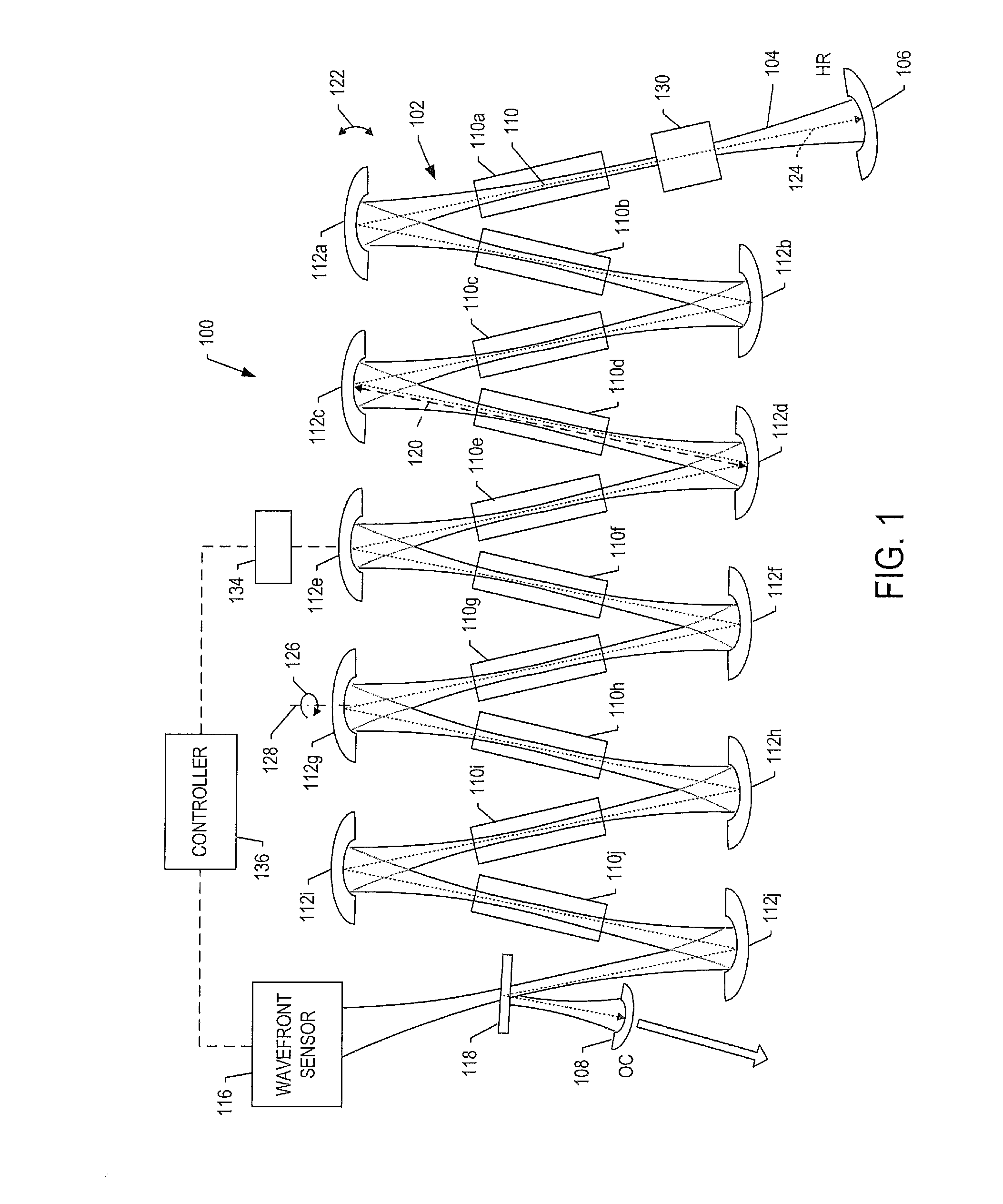
[0020]FIG. 1 illustrates a laser resonator 100 including a number of optical elements according to one example embodiment. As shown, the laser resonator 100 includes a cavity 102 in which a beam 104 may propagate. The cavity 102 may be bo...


PUM


Abstract

A laser resonator is provided that includes a cavity bounded by an end mirror and output coupler, and one or more gain media between the end mirror and output coupler. The laser resonator also includes a modal corrector mirror between the end mirror and output coupler. The modal corrector mirror includes a controllable-profile faceplate including an optically-treated front surface, and an array of static actuators. Each static actuator includes an adjustable element, and a compliant mechanism located between the adjustable element and faceplate. The adjustable element is configured to exert a selectable, localized push-pull force on the faceplate via the compliant mechanism, and the compliant mechanism is configured to scale the respective force.

Description

TECHNOLOGICAL FIELD[0001]The present disclosure relates generally to laser resonators and, in particular, to correcting aberrations in laser resonators.BACKGROUND[0002]Adaptive Optics (AO) is a term commonly given to the improvement of the performance of optical systems by reducing the effect of varying wavefront distortions. It is used in astronomical telescopes and laser communication systems to remove the effects of atmospheric turbulence, and in imaging systems to reduce the improve image sharpness. AO systems work by measuring distortions in a path and using a device to compensate for them. The extent to which AO can effectively improve resolution, however, fundamentally depends on its ability to accurately measure, track and correct the distortions.[0003]Current AO systems have limited ability to correct errors that have relatively higher spatial-frequency content. This higher frequency content may contribute to scatter due to the angular spectrum associated with it. Wavefront...

Claims


Application Information

Patent Timeline
IPC IPC(8): H01S3/098G02B7/185
CPCG02B26/0825H01S3/07H01S3/08059H01S3/0813H01S3/086H01S3/105H01S3/1307H01S3/139
Inventor ROSSBACH, DENNIS
Owner THE BOEING CO
Why Eureka
Try Eureka