Coupling device having a structured reflective surface for coupling input/output of an optical fiber

Inactive Publication Date: 2013-12-05
SENKO ADVANCED COMPONENTS
View PDF9 Cites 58 Cited by
  • Summary
  • Abstract
  • Description
  • Claims
  • Application Information

AI Technical Summary

Benefits of technology

[0010]The present invention provides a coupling device for physically and optically coupling an input/output end of an optical fiber for routing optical signals. The device may be implemented for physically and opticall

Problems solved by technology

The transmitters and receivers and associated structures having the connection ports are therefore generally bulky, which take up significant space, thereby making them not suitable for use in smaller electronic devices.
Heretofore, the coupling structure

Method used


Image

  • Coupling device having a structured reflective surface for coupling input/output of an optical fiber
  • Coupling device having a structured reflective surface for coupling input/output of an optical fiber
  • Coupling device having a structured reflective surface for coupling input/output of an optical fiber

Examples


Embodiment Construction

[0029]This invention is described below in reference to various embodiments with reference to the figures. While this invention is described in terms of the best mode for achieving this invention's objectives, it will be appreciated by those skilled in the art that variations may be accomplished in view of these teachings without deviating from the spirit or scope of the invention.

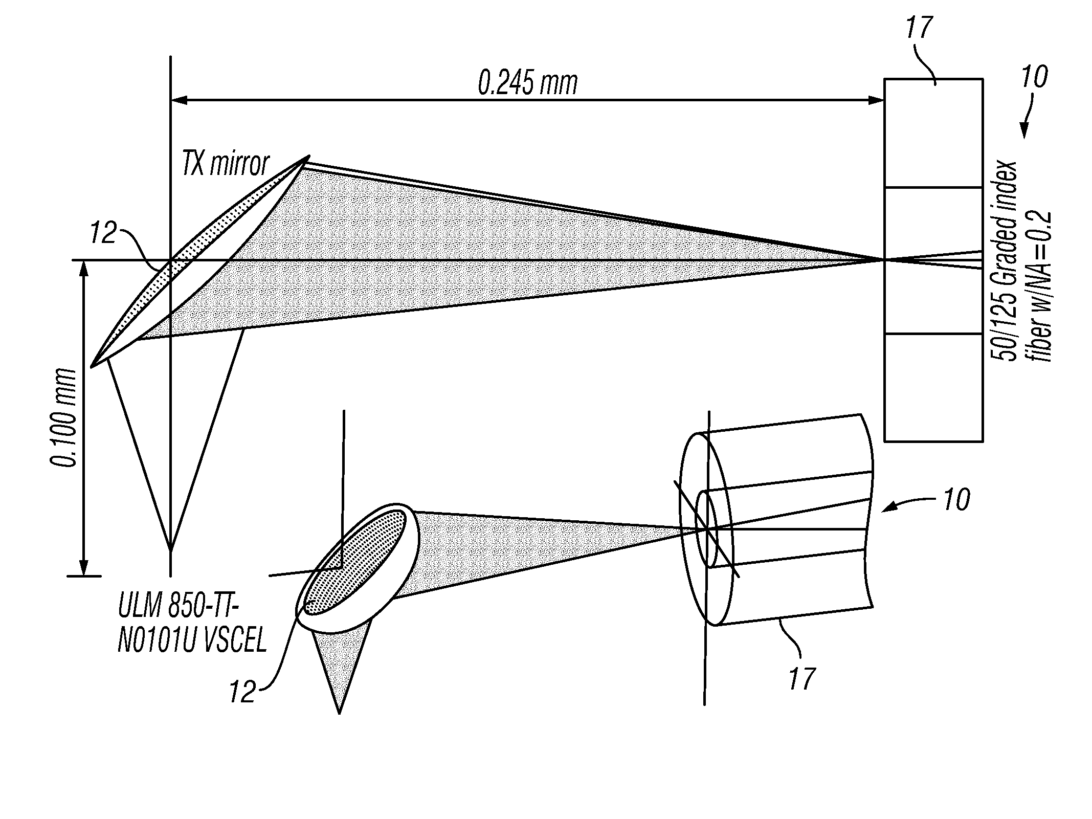
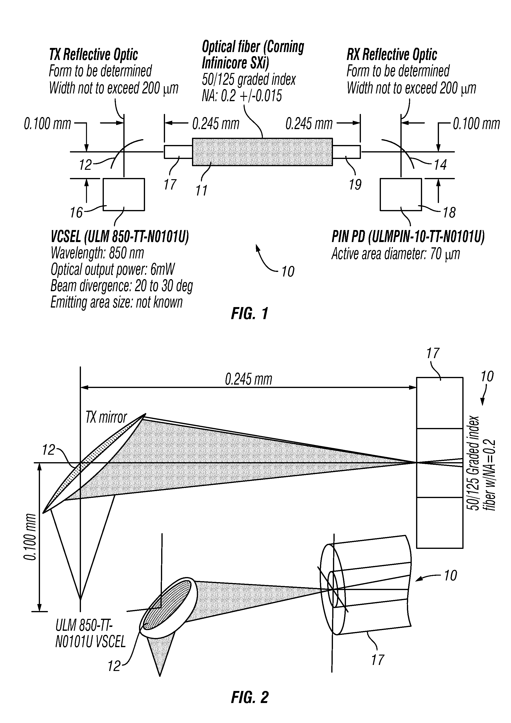
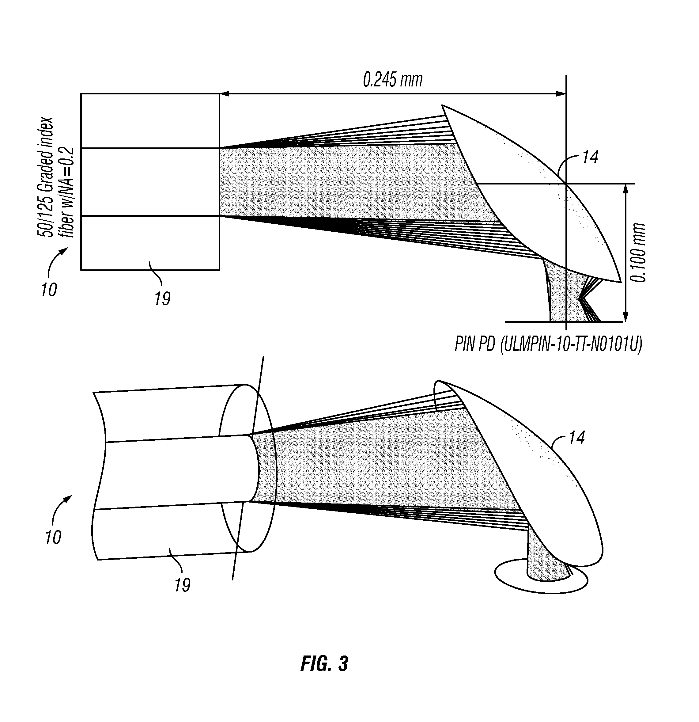
[0030]The present invention provides a coupling device for physically and optically coupling an input / output end of an optical fiber for routing optical signals. The device may be implemented for physically and optically coupling an optical fiber to an optical receiver and / or transmitter, which improves manufacturability, ease of use and reliability at reduced costs, thereby overcomes many of the drawbacks of the prior art structures. According to the present invention, the coupling device includes a structured surface that functions as an optical element that directs light to / from the input / output ends of...


PUM

PropertyMeasurementUnit
Distanceaaaaaaaaaa
Reflectionaaaaaaaaaa

Abstract

A coupling device for physically and optically coupling an input/output end of an optical fiber for routing optical signals, to and from optical receiver and/or transmitter. The coupling device includes a structured reflective surface that functions as an optical element that directs light to/from the input/output ends of the optical fiber by reflection, and an optical fiber retention groove structure that positively receives the optical fiber in a manner with the end of the optical fiber at a defined distance to and aligned with the structured reflective surface. The open structure of the structured reflective surface and fiber retention structure lends itself to mass production processes such as precision stamping. The coupling device can be attached to an optical transmitter and/or receiver, with the structured reflective surface aligned to the light source in the transmitter or to the detector in the receiver, and adapted in an active optical cable.

Description

PRIORITY CLAIM[0001]This application claims the priority of U.S. Provisional Patent Application No. 61 / 606,885 filed on Mar. 5, 2012, which is fully incorporated by reference as if fully set forth herein. All publications noted below are fully incorporated by reference as if fully set forth herein.BACKGROUND OF THE INVENTION[0002]1. Field of the Invention[0003]The present invention relates to fiber optic signal transmission, in particular a device for physically and optically coupling an optical fiber for routing optical signals.[0004]2. Description of Related Art[0005]Given the increasing bandwidth requirements for modern day data transmission (e.g., for high definition video data), fiber optic signal transmissions have become ubiquitous for communicating data. Optical signals are transmitted over optical fibers, through a network of optical fibers and associated connectors and switches. The optical fibers demonstrate a significantly higher bandwidth data transmission capacity and ...

Claims


Application Information

Patent Timeline
IPC IPC(8): G02B6/26B21D22/00G02B6/42
CPCG02B6/262G02B6/4214B21D22/00G02B6/4206G02B6/42G02B6/4243G02B6/4263G02B6/4295
Inventor LI, SHUHEVALLANCE, ROBERT RYANHII, KING-FUGEAN, MATTHEWBARNOSKI, MICHAEL K.DANNENBERG, RAND
Owner SENKO ADVANCED COMPONENTS
Why Eureka
Try Eureka