Economizer HVAC and control system

a control system and hvac technology, applied in ventilation systems, lighting and heating apparatus, heating types, etc., to achieve the effect of reducing the potential for termination errors, reducing technician effort, and simplifying the way the system is installed

Inactive Publication Date: 2013-12-05
DAVIS DAVID
View PDF0 Cites 33 Cited by
  • Summary
  • Abstract
  • Description
  • Claims
  • Application Information

AI Technical Summary

Benefits of technology

[0013]The control system of the disclosed technology can also include an economizer fail-safe signal, which is activated when an off normal damper position is detected. The system then attempts to allow the system to run in non-economizing mode. When the fail-safe signal is generated, the economizer mode will be turned off and the non-economizing mode activated. All embodiments prevent continued use of an economizer mode when dampers are in a fault condition, such as when the intake damper is in the wrong position for the economizer mode. This would stop the incorrect running of the economizer mode even if the operator of the system is not aware that the error had occurred. All embodiments also prevent non-economizing mode operation if dampers are not identified in the proper position to support non-economizing operation.
[0018]The complexity problem is addressed in the disclosed technology by a connection methodology that eliminates technician effort and greatly simplifies the way the system is installed. Each of the control cables have a first end and a second end, with the first end connecting to the control module and the second end connecting to one of the required system components, which are the furnace control board, the dampers, and the external temperature sensor. Each of the cables are terminated with a fitting which is geometrically coded so that it only fits in one receptacle in the control module, and it can only fit in the fitting in one orientation. For this reason, each of the cables can only fit in the control module in the proper interfitting connection and only one orientation of the fitting is possible this reduces the potential for termination errors by one half. This feature alone makes the disclosed technology much more fool proof and economically efficient to set up.
[0019]The damper cable is particularly prone to errors during installation if it is left to a technician to make all the connections for proper operation in a difficult environment. In connecting the control module to each damper, for instance, there are power connections to the damper motors, there are connections to the position sensors of the damper, and connections in between damper switches creating the circuit that provides status logic. This typically results in the need to connect twenty six wires and if any one of them is connected to the wrong attachment point the system will be in error. This is one of the reasons why prior art of economizer systems have such a high error rate. Not only does the use of geometrically coded and pre-wired cables guarantee that the system is set up correctly, but it also enables errors in the damper positioning to be detected and reported to the user in the conditioned space, and greatly reduces the amount of time a technician spends in the hot environment of an attic. Each of these are features which are not found in the prior art.

Problems solved by technology

No other split-system economizer provides two sensors of damper position.

Method used


Image

  • Economizer HVAC and control system
  • Economizer HVAC and control system
  • Economizer HVAC and control system

Examples


Embodiment Construction

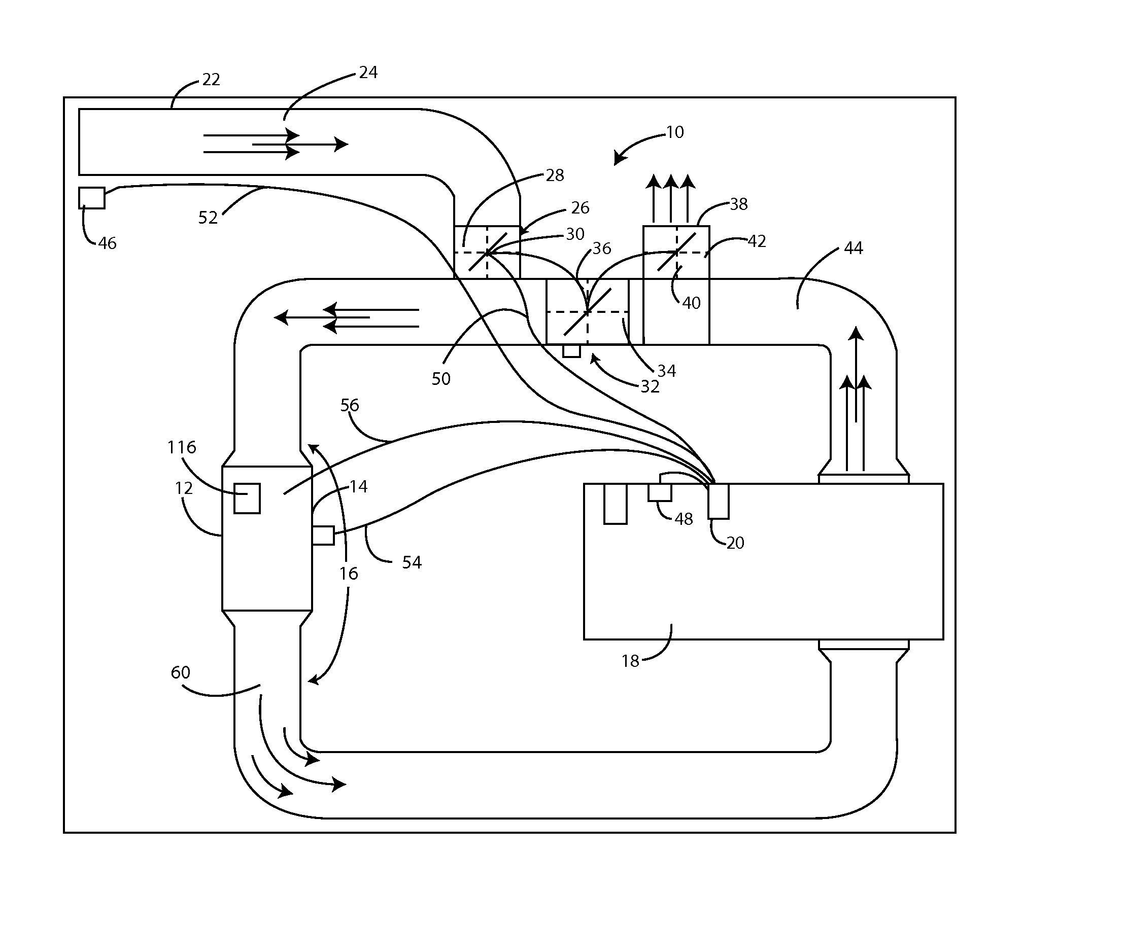
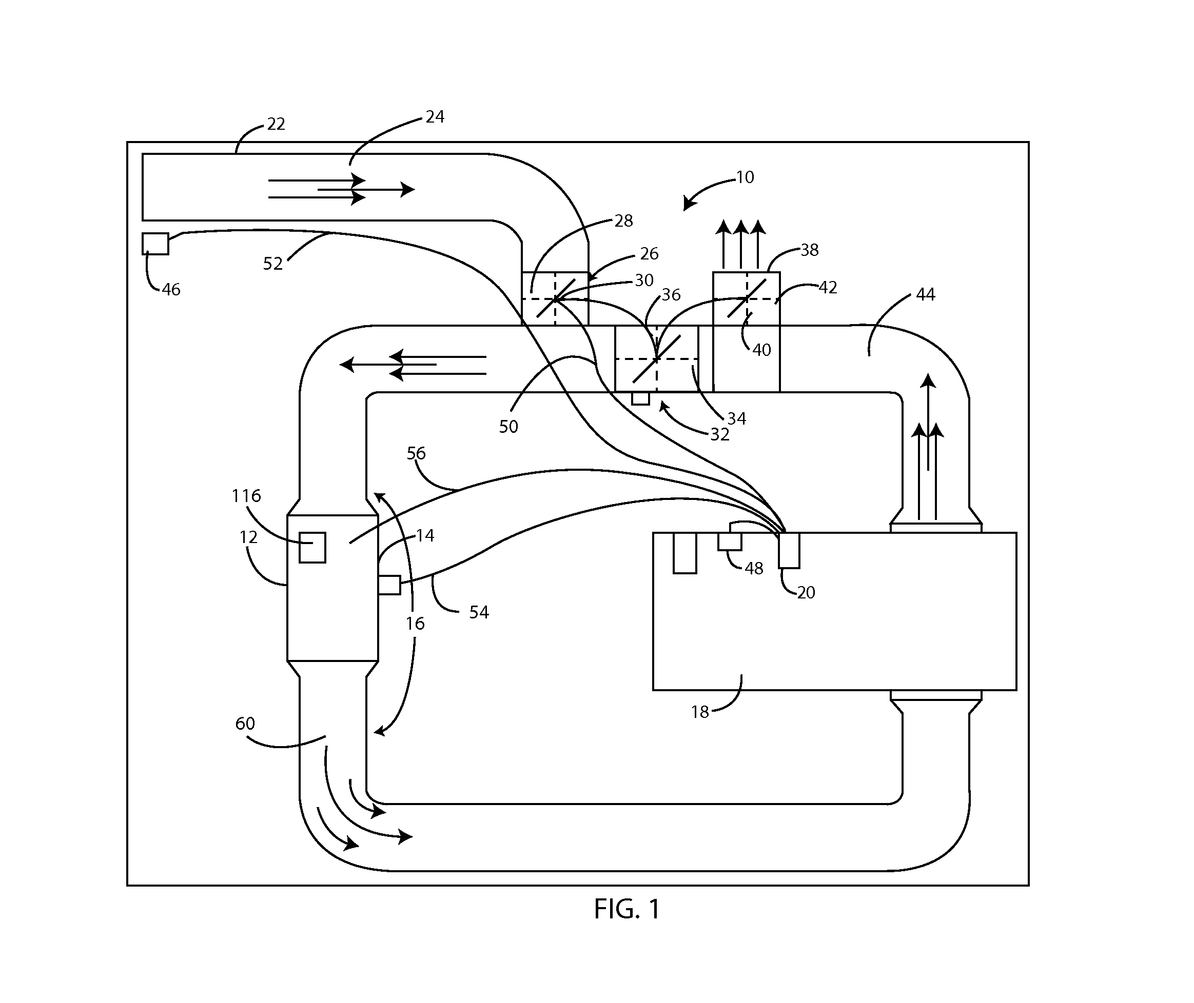
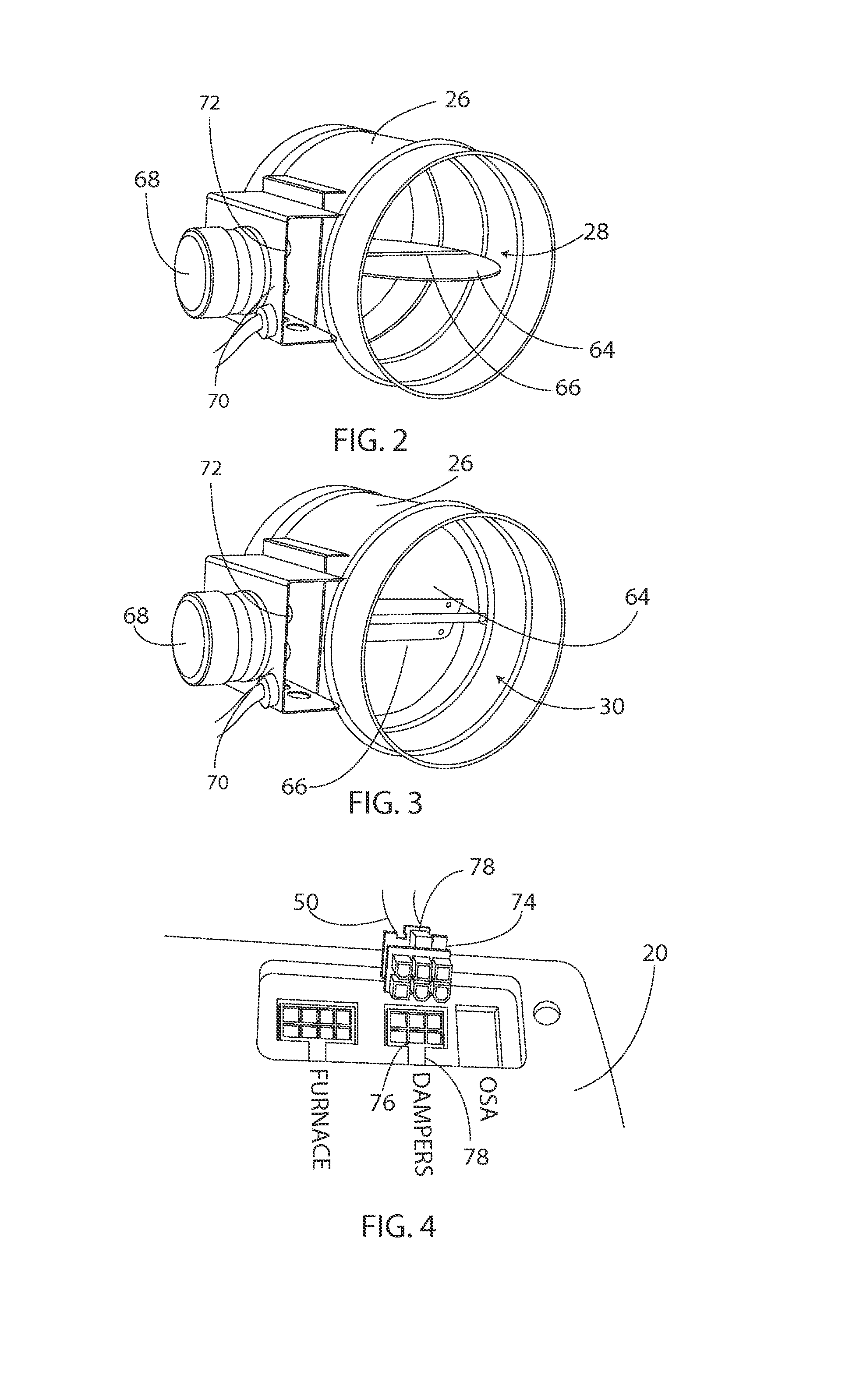
[0028]FIG. 1 shows the HVAC system of the disclosed technology, which provides for economizer mode operation of the HVAC system 10. The HVAC system 10 includes a circulation fan 12, cooling unit 14, and a network of air delivery ducts 16. The HVAC system 10 provides heating and cooling for a conditioned space 18. A user controls the economizing portion of the HVAC system 10 with control module 20. The HVAC system 10 includes an outside air intake duct 22 to provide outside airflow 24 to the conditioned space 18. Also included is a first, or intake, damper 26. The first damper 26 has two positions: a first, or closed, position 28, and a second, or open, position 30. The HVAC system 10 may have an isolation damper 32, operable between an open position 34 and a closed position 36, and a third (relief) damper 38, operable between a closed position 42 and an open position 40. A preferred embodiment of the control system and HVAC system uses three dampers. Both the second (isolation) damp...


PUM


Abstract

An HVAC and control system with an economizer mode and continuous damper position verification. Three dampers are provided with a control module that accepts inputs from multiple temperature sensors and a user, and which monitors and reports the position and off-normal operation of multiple dampers.

Description

PRIORITY / CROSS-REFERENCE TO RELATED APPLICATIONS[0001]This application claims the benefit of U.S. Provisional Application No. 61 / 654,561, filed Jun. 1, 2012, the disclosure of which is incorporated by this reference.BACKGROUND[0002]The disclosure generally relates to the field of heating, ventilation, and air conditioning (HVAC) systems. In the world of HVAC, cooling is provided when heat in the air within a conditioned space (such as the interior of a building) is removed by circulating the air through a cooling coil (i.e., an “air conditioner”) and then re-delivered to the conditioned space to keep the space at the desired temperature. Some HVAC systems have an economizer, which is a subsystem that introduces outside air into the building when the outside air is cool enough that it can be used to either supplement or replace mechanical cooling. An HVAC system with an economizer typically has a set of three actuator-driven dampers. Dampers are devices that function to regulate airf...

Claims


Application Information

Patent Timeline
Patent Type & Authority Applications(United States)
IPC IPC(8): F24F11/00
CPCF24F11/0001F24F2011/0002F24F2011/0006F24F11/30F24F2110/00F24F2110/12F24F11/32F24F2140/40F24F11/65F24F11/46F24F11/38
Inventor DAVIS, DAVID
Owner DAVIS DAVID
Why Eureka
Try Eureka