System and method for controlling velocity of a vehicle

Active Publication Date: 2013-12-05
GE GLOBAL SOURCING LLC
View PDF2 Cites 18 Cited by
  • Summary
  • Abstract
  • Description
  • Claims
  • Application Information

AI Technical Summary

Benefits of technology

[0006]In one embodiment, a control system includes an onboard controller, a location determination system, and a speed data sensor. The controller is configured to identify a designated area along a route being traveled by a vehicle. The designated area includes one or more of a downhill section of the route, an airflow restricted area of the route, a banked section of the route, a section of the route to be cleaned, an adverse environmental condition area of the route, an adverse vehicular condition area of the route, a section of the route where travel is restricted by one or more regulatory or legal restrictions, or a section of the route where travel is restricted due to a condition of the route. The designated area is associated with an operating rule that requires the vehicle to travel at least as fast as a designated lower speed limit. The location determination system is configured to monitor actual locations of the vehicle as the vehicle travels along the route. The speed data sensor is configured to obtain speed data representative of an actual velocity of the vehicle. The controller also is configured to restrict control of the vehicle such that the actual velocity of the vehicle is at leas

Problems solved by technology

With respect to locomotives, one such rule is a limitation on how slowly an operator can control the locomotive to move when an air brake is partially applied.
For example, if the operator were allowed to continue bleeding off the air in the air brakes, then there may be insufficient air pressure to operate the brakes should the need arise (e.g., while the compressor is working to increase the air pressure

Method used


Image

  • System and method for controlling velocity of a vehicle
  • System and method for controlling velocity of a vehicle
  • System and method for controlling velocity of a vehicle

Examples


Embodiment Construction

[0017]One or more embodiments of the inventive subject matter described herein relate to systems and methods for controlling velocities of vehicles as the vehicles travel along a route in order to prevent the vehicles from traveling slower than designated lower speed limits associated with designated areas along the route. The lower speed limits may be part of operating rules that limit how slowly vehicles can travel through the designated areas (e.g., without triggering automatic braking) and can be established for various reasons, such as safety, efficiency (e.g., of moving the vehicles through a network of the routes), and the like.

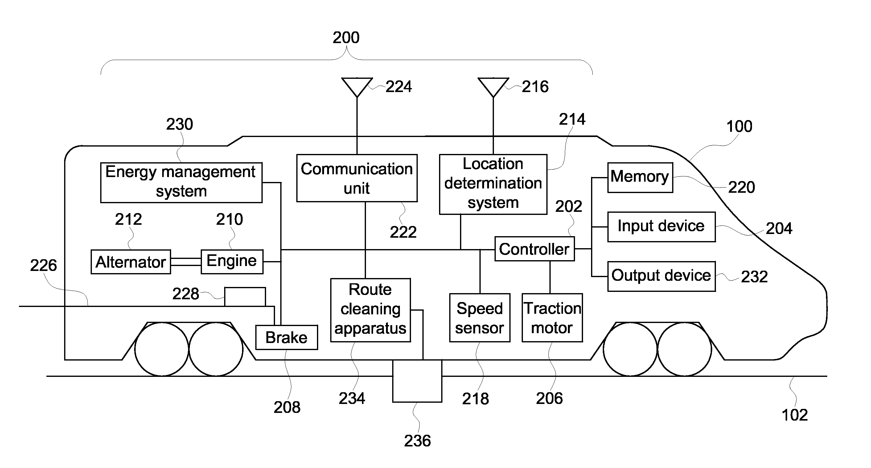
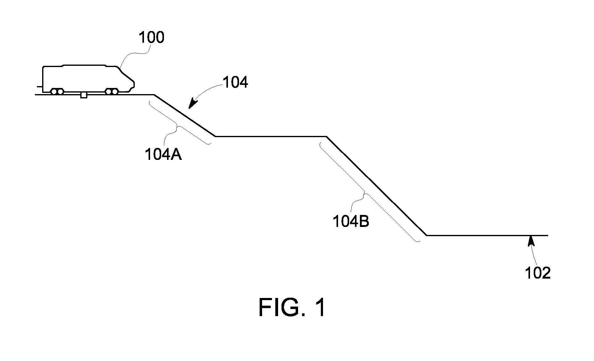
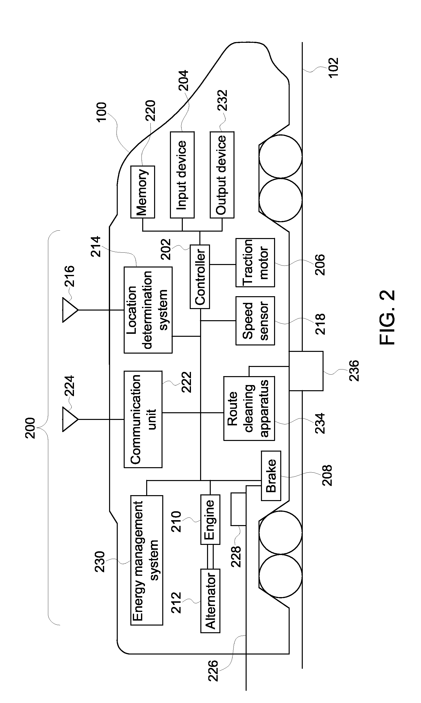
[0018]FIG. 1 is a schematic diagram of a vehicle 100 traveling along a route 102 in accordance with one embodiment of the inventive subject matter. The vehicle 100 is illustrated as a rail vehicle (e.g., a locomotive), but alternatively may be another type of rail vehicle, an off highway vehicle other than a rail vehicle, an automobile, marine vessel, ...


PUM


Abstract

A control system includes an onboard controller, a location determination system, and a speed sensor. The controller identifies a designated area along a route that includes a downhill section, an airflow restricted area, a banked section, a section to be cleaned, an adverse environmental area, an adverse vehicular condition area, and/or a section where travel is restricted. The designated area is associated with an operating rule that requires the vehicle to travel at least as fast as a lower speed limit. The location determination system monitors actual locations of the vehicle as the vehicle travels along the route. The speed sensor obtains speed data representative of an actual velocity of the vehicle. The controller restricts control of the vehicle such that the actual velocity of the vehicle is at least as fast as the lower speed limit of the designated area when the vehicle is in the designated area.

Description

FIELD[0001]Embodiments of the inventive subject matter relate to vehicle control.BACKGROUND[0002]Vehicles travel to move cargo and / or passengers along a route and / or network of interconnected routes. These vehicles may operate according to rules to ensure the safety of the cargo, passengers, and operators of the vehicles. These rules may differ from the regulations or laws created by governmental or regulatory entities. For example, while governments and regulatory bodies may create speed limits that restrict how fast vehicles may travel in order to reduce accidents and / or the severity of accidents caused by vehicles traveling too fast, other entities may create rules to dictate operation of the vehicles. As one example, a company that owns and operates a locomotive may create rules that restrict how the locomotive can be operated in order to ensure the safety of the operator, passengers, and cargo, and / or to reduce wear on the track, cars, or locomotive.[0003]With respect to locomo...

Claims


Application Information

Patent Timeline
IPC IPC(8): G06F7/00B60T7/12
CPCB60T13/665B60T17/228B61L25/02B61L25/021B60T7/18B61L27/10
Inventor COOPER, JARED KLINEMANELDREDGE, DAVIDPELTZ, DAVIDBRAND, JOHNWAWRZYNIAK, FRANKBREMMER, ROBERTBARRETT, MICHAELDAUM, WOLFGANG
Owner GE GLOBAL SOURCING LLC
Why Eureka
Try Eureka