Check patentability & draft patents in minutes with Patsnap Eureka AI!

Apparatus for oscillation-decoupled mounting of an electric motor, in particular a blower motor

a technology of decoupling elements and electric motors, which is applied in the direction of mechanical apparatus, machines/engines, liquid fuel engines, etc., can solve the problems of significant noise development, reduced functionality of electric motors, and significant reduction of rigidity of installed decoupling elements

Inactive Publication Date: 2013-12-12
ROBERT BOSCH GMBH
View PDF8 Cites 5 Cited by
  • Summary
  • Abstract
  • Description
  • Claims
  • Application Information

AI Technical Summary

Benefits of technology

The invention is an apparatus for mounting an electric motor with a decoupling system that prevents collisions between components and ensures proper motor functioning even at high temperatures. The apparatus includes a casing part that extends outward from the motor and accommodates connecting lugs. The casing part has two or more transverse webs that extend from the casing part to the outer part of the decoupling element, which improves decoupling and damping of oscillations. The design of the outer part of the apparatus makes it easy to install in the outer housing. The technical effects of the invention include better protection against damage, improved performance, and lower operational noise.

Problems solved by technology

The decoupling elements act as rubber springs and are designed to achieve a low-vibration and noise-damping effect during the operation of the electric motor; however, when the operating temperature of the electric motor is high, the rigidity of the installed decoupling elements significantly decreases.
A severe deformation of the decoupling elements can then result, wherein the risk of a collision between connecting lugs and outer housing arises, which can lead to significant noise development, the reduced functionality of the electric motor and even in the worst-case scenario to a breakdown of the electric motor.

Method used


Image

  • Apparatus for oscillation-decoupled mounting of an electric motor, in particular a blower motor
  • Apparatus for oscillation-decoupled mounting of an electric motor, in particular a blower motor
  • Apparatus for oscillation-decoupled mounting of an electric motor, in particular a blower motor

Examples


Embodiment Construction

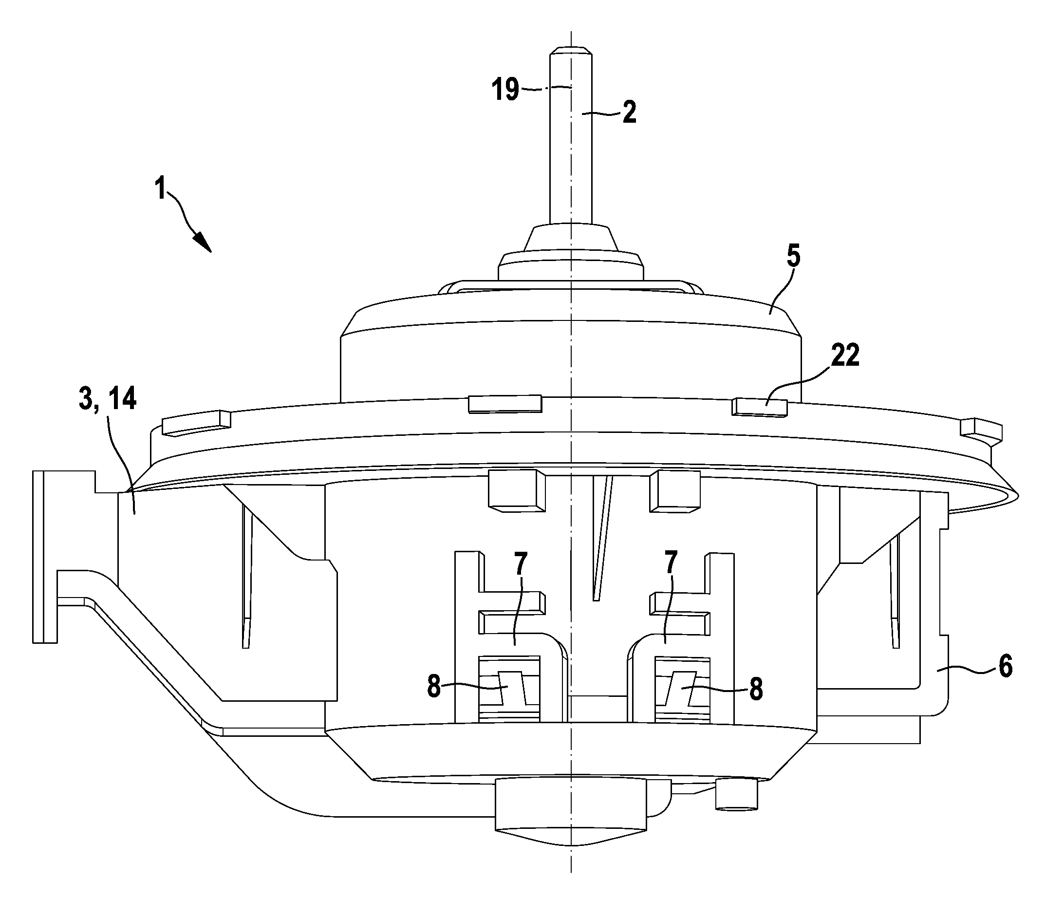
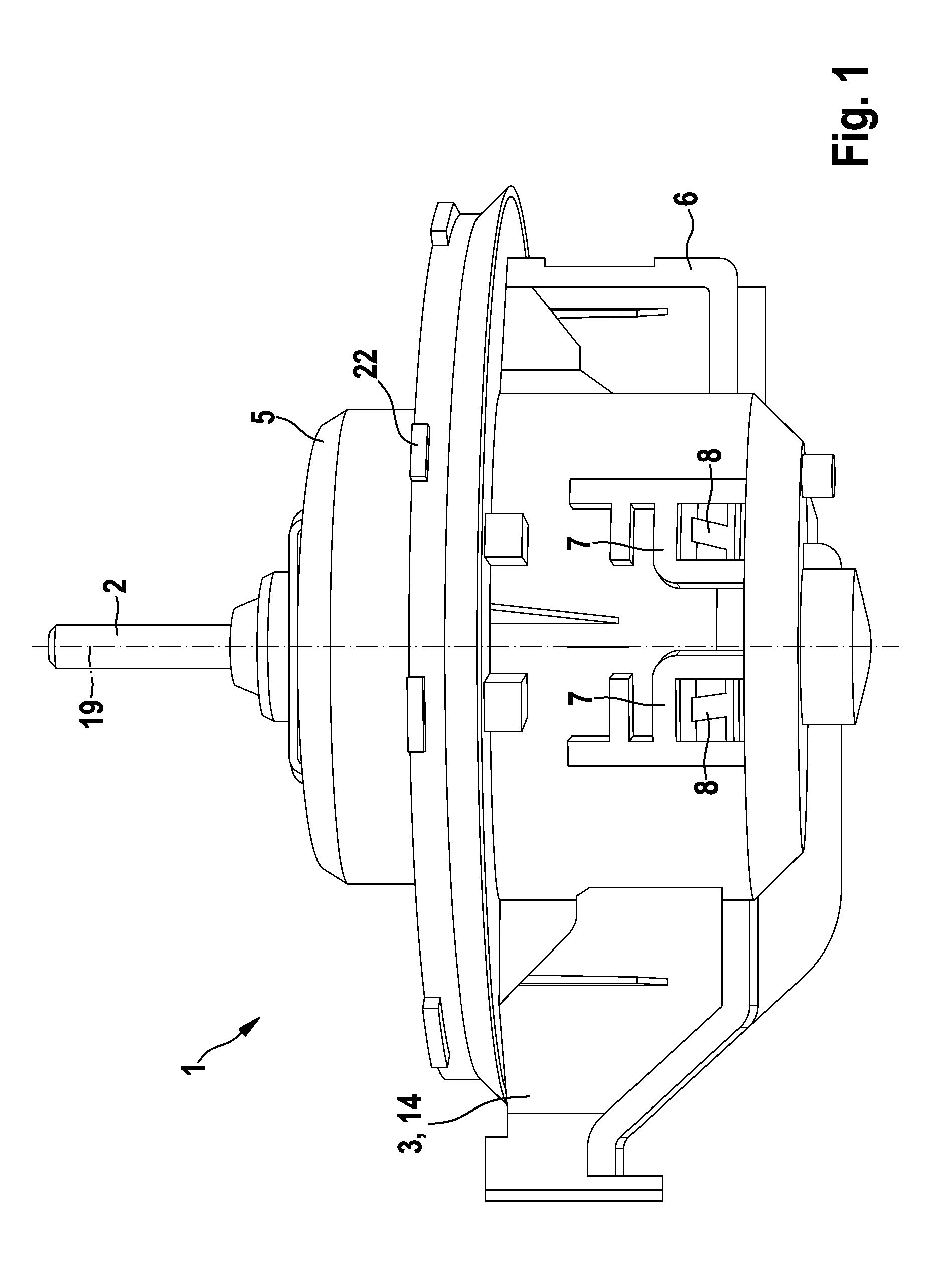
[0022]FIG. 1 shows an electric motor 1 as it is used in an air-conditioning fan of a motor vehicle. The electric motor 1 drives a rotor or, respectively, a rotor shaft 2 in a known manner, on which a radially compressing fan wheel, which is not described here in detail, is mounted, said fan wheel generating an air flow in a fan duct. The electric motor 1 serving as blower motor is mounted in the fan duct, via which the vehicle interior is then supplied with fresh air. The electric motor 1 is part of a blower module 3 depicted in FIG. 1. The electric motor 1 belongs to the assembly of the blower module 3, the former being preferably embodied as a permanently self-excited DC motor. The electric motor 1 has a pole housing not depicted in FIG. 2, which is referred to below as a motor housing 4, which is embedded in a plastic housing, referred to below as outer housing 5, 6, via three connecting points. The pole housing 4 comprises in a known manner in the interior thereof a plurality of...


PUM


Abstract

It is known to mount an electric motor (1), in particular a blower motor, with oscillation decoupling. The electric motor (1) has a motor housing (4), in particular a pole housing, which has at least one connecting lug (10), which protrudes radially from the motor housing (4) and on which a decoupling element (20) is fitted, via which decoupling element the motor housing (4) is supported on an outer housing (5, 6). In order to rule out the risk of a collision between the connecting lug (10) and the outer housing (5, 6), the invention proposes an apparatus for oscillation-decoupled mounting, in which the decoupling element (20) surrounds the connecting lug (10; 11, 12) in the form of a sleeve with a casing part (21), wherein the casing part (21) is supported, via at least one web (30, 31; 40, 41; 50, 51; 55, 56), on an outer part (26), which surrounds the casing part (21) in the form of a frame and is accommodated in the outer housing (5, 6), which is preferably formed in two parts. The apparatus for oscillation-decoupled mounting of an electric motor is intended in particular for blower motors of motor vehicle air conditioning systems.

Description

BACKGROUND OF THE INVENTION[0001]The present invention relates to an apparatus for the oscillation-decoupled mounting of an electric motor, in particular a blower motor. The electric motor has a motor housing, in particular a pole housing, which has at least one connecting lug, which protrudes radially from the motor housing and on which a decoupling element is fitted, via which decoupling element the motor housing is supported on an outer housing.[0002]The decoupling elements are inserted as resilient intermediate layers between a motor housing, in particular a pole housing of the electric motor, and the attachment points of the motor housing in an outer housing which surrounds said motor housing, is preferably formed in two parts and is made from plastic. The decoupling elements act as rubber springs and are designed to achieve a low-vibration and noise-damping effect during the operation of the electric motor; however, when the operating temperature of the electric motor is high,...

Claims


Application Information

Patent Timeline
IPC IPC(8): H02K5/24
CPCH02K5/24F04D27/008F04D29/668F16F1/373F16F1/38F16F15/12
Inventor BARKIC, DUBRAVKOMAHFOUDH, SAMIRRUDIGIER, MARKUS
Owner ROBERT BOSCH GMBH
Features
  • R&D
  • Intellectual Property
  • Life Sciences
  • Materials
  • Tech Scout
  • Unparalleled Data Quality
  • Higher Quality Content
  • 60% Fewer Hallucinations
Learn More