
Bend-insensitive optical fiber having small coating diameter and optical cable comprising the same

a technology of optical fiber and coating diameter, applied in the direction of glass optical fibre, cladded optical fibre, instruments, etc., can solve the problems of high bending loss, difficult installation close to the corner, and difficult handling of home (ftth) , to achieve the effect of reducing manufacturing cost, minimizing volume, and improving bending loss characteristics

Inactive Publication Date: 2013-12-12
LG CABLE LTD (KR)
View PDF11 Cites 235 Cited by
  • Summary
  • Abstract
  • Description
  • Claims
  • Application Information

AI Technical Summary

Benefits of technology

The patent is about a new type of optical fiber that is resistant to bending and has a small coating. This fiber can be used in a multicore optical cable, which can be manufactured more cost-effectively. The main benefit is that it reduces bending loss, which means that the signal loss is minimized when the fiber is bent. This means that more data can be transmitted over longer distances without any signal loss.

Problems solved by technology

When compared with other media for data transmission such as a copper line, an optical fiber is advantageous in terms of loss and bandwidth, but is disadvantageous in that it is difficult to handle.
In particular, a conventional optical fiber applied to fiber to the home (FTTH) exhibits a high bending loss as a result of a small bend, and thus, is difficult to install close to the corner or makes it awkward to use an organizer having a small bend diameter.
Disadvantageously, there is a difference in MFD between the SI optical fiber and a conventional optical fiber, resulting in incompatibility.
Generally, it is known that a depressed index optical fiber has a limitation in improving the bending loss and thus its bendable diameter is limited to about 7.5 mm.
However, these arts have a reduction in productivity due to a hole forming process, and are evaluated as being unsuitable for mass production.
However, the bubbles are random which results in non-uniform bending characteristics in the lengthwise direction and the circumferential direction of an optical fiber.
However, this art has a complex index profile, which makes it difficult to ensure reproducibility and is unfavorable for mass production.
However, this optical fiber structure is not suitable for a multicore optical cable being in demand these days, and increases the manufacturing cost of an optical cable.

Method used


Image

  • Bend-insensitive optical fiber having small coating diameter and optical cable comprising the same
  • Bend-insensitive optical fiber having small coating diameter and optical cable comprising the same
  • Bend-insensitive optical fiber having small coating diameter and optical cable comprising the same

Examples


Embodiment Construction

[0042]Hereinafter, the present invention will be described in detail. Prior to the description, it should be understood that the terms used in the specification and appended claims should not be construed as limited to general and dictionary meanings, but interpreted based on the meanings and concepts corresponding to technical aspects of the present invention on the basis of the principle that the inventor is allowed to define terms appropriately for the best explanation.

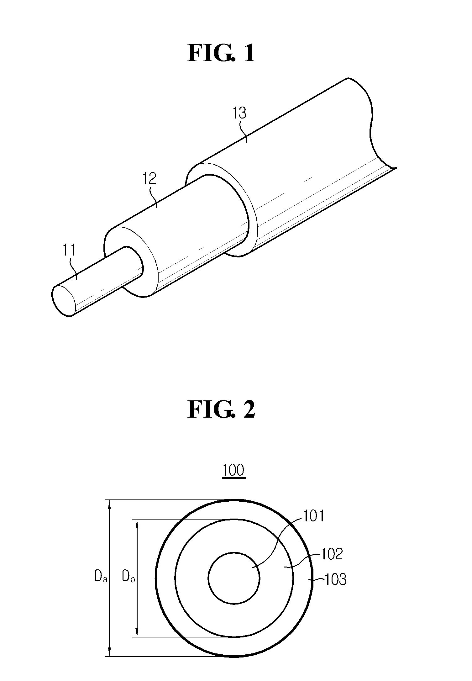
[0043]FIG. 2 is a cross-sectional view illustrating a bend-insensitive optical fiber according to a preferred embodiment of the present invention.

[0044]Referring to FIG. 2, a bend-insensitive optical fiber 100 according to a preferred embodiment of the present invention includes a core 101, a cladding 102, and a coating layer 103 having an outer diameter Da of 240 μm or less. Here, the present invention is not limited to a specific thickness ratio between the core 101, the cladding 102, and the coating layer 103 di...


PUM


Abstract

Provided is a bend-insensitive optical fiber including a core centered at the optical fiber, a cladding surrounding the core and having a lower refractive index than the core, a coating layer surrounding the cladding, and a region formed in the cladding and having a lower refractive index than the cladding, wherein the coating layer has a multilayered structure and a total outer diameter of 240 μm or less, and a bend-insensitive optical cable comprising the same.

Description

TECHNICAL FIELDCross-Reference to Related Application[0001]This application claims priority from Korean Patent Application No. 10-2011-0013268, filed on Feb. 15, 2011, the entire disclosure of which is incorporated herein by reference for all purposes.[0002]The present invention relates to a bend-insensitive optical fiber and an optical cable, and more particularly, to a bend-insensitive optical fiber having a low bending loss through the improvement in internal structure and material properties, and an optical cable comprising the same.BACKGROUND ART[0003]An optical fiber has optical properties that vary depending on the refractive index profile of a core and a cladding, and generally, an optical fiber having desired properties may be fabricated by controlling the refractive index profile.[0004]When compared with other media for data transmission such as a copper line, an optical fiber is advantageous in terms of loss and bandwidth, but is disadvantageous in that it is difficult to...

Claims


Application Information

Patent Timeline
IPC IPC(8): G02B6/036
CPCG02B6/03694G02B6/443G02B6/03633G02B6/02395
Inventor YANG, EUN-JEONGPARK, JI-SANG
Owner LG CABLE LTD (KR)
Learn More