Spray Plume Position Feedback for Robotic Motion to Optimize Coating Quality, Efficiency, and Repeatability

a robotic motion and spray plume technology, applied in the field of coatings, can solve the problems of not meeting the requirements for which they are configured, and affecting the efficiency of coatings, etc., and affecting the quality of coatings. the effect of repeatability and repeatability

Active Publication Date: 2013-12-12
GENERAL ELECTRIC CO
View PDF8 Cites 6 Cited by
  • Summary
  • Abstract
  • Description
  • Claims
  • Application Information

AI Technical Summary

Problems solved by technology

Over time, the components of such systems may deteriorate, go out of alignment, or otherwise fail to meet the requirements for which they are configured.
When several systems are installed in various sites, similar thermal spraying equipment may apply material in a variable manner due to variations in installation methods and / or conditions at each respective site, and therefore the application of material may not be consistent and may be outside of specifications in some sites despite the intended design.
Moreover, while one or more components used to align a system may be in correct alignment and position, the resulting spray may not be applying material where it is intended to go.
For example, a thermal spray torch may be correctly aligned such that a centerline of the torch is aligned with a particular point, but due to other equipment variations, such as internal components of the torch, the resulting spray may not be aligned with the centerline of the torch, and therefore material may not be applied to the correct area despite the apparent alignment of the torch.
When coatings are applied using components or processes that fail to meet their specified or desired requirements, manual reworking of the coated item may be required or the item may be put into use without detecting that it has not been properly coated by the thermal spray system.
This problem is especially acute when coating three-dimensional items as proper positioning of a spray plume is especially important to provide the proper coating to all areas of such an item.
For turbine components, and any thermal sprayed item in general, improperly applied coatings may result in higher costs, longer production times, and shorter lifespans for the coated items.

Method used


Image

  • Spray Plume Position Feedback for Robotic Motion to Optimize Coating Quality, Efficiency, and Repeatability
  • Spray Plume Position Feedback for Robotic Motion to Optimize Coating Quality, Efficiency, and Repeatability
  • Spray Plume Position Feedback for Robotic Motion to Optimize Coating Quality, Efficiency, and Repeatability

Examples


Embodiment Construction

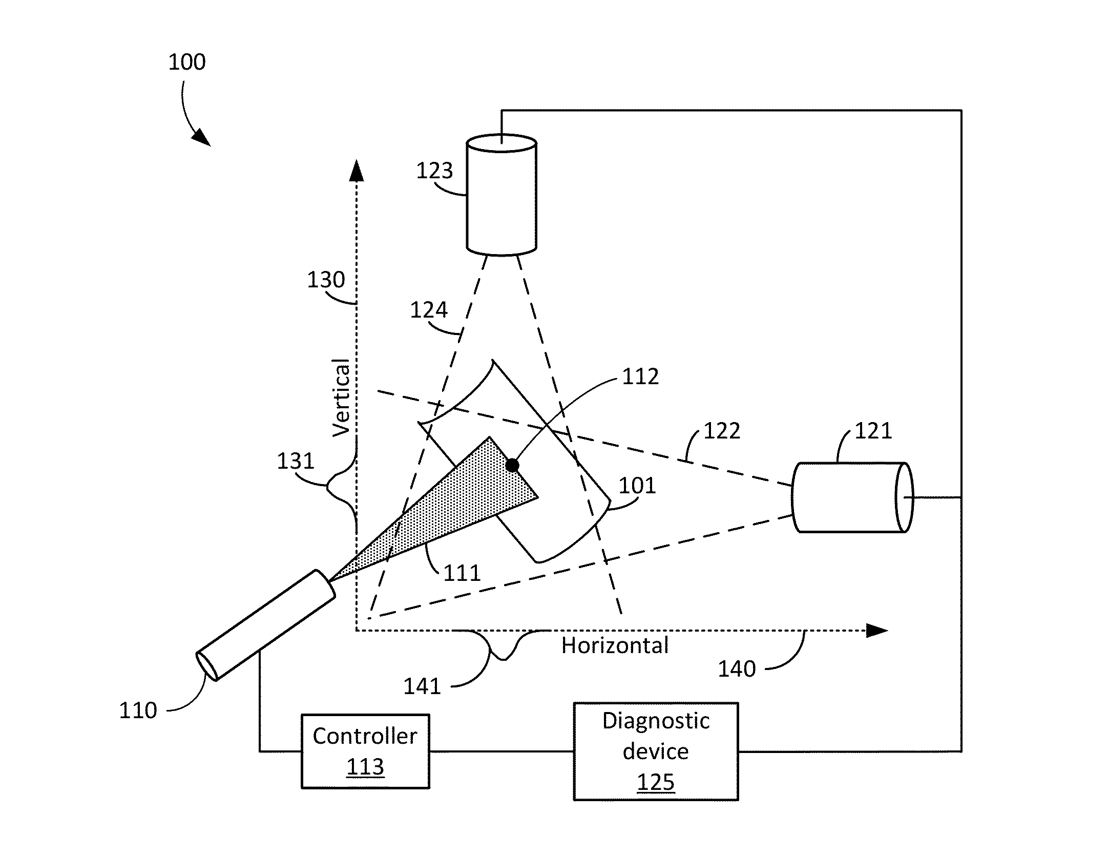
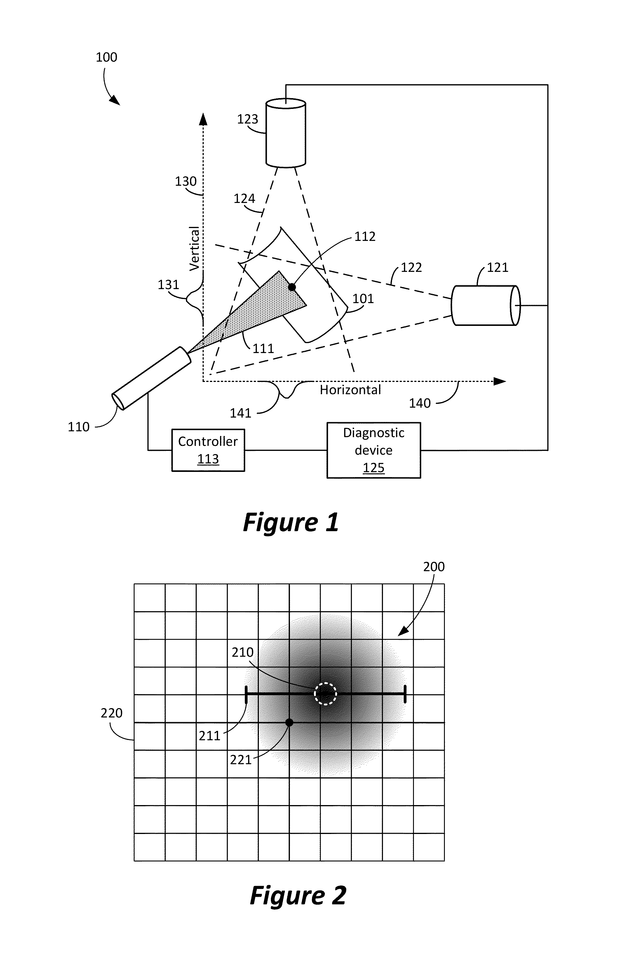
[0016]In an embodiment, a coating, such as one or more layers of an environmental barrier coating (EBC), may be applied to an article using a thermal spray system. The article may be any article, including, but not limited to, a gas turbine blade, and the article may be constructed from any material, including, but not limited to, a ceramic matrix composite (CMC) and a Ni / Fe / Co based alloys. While the present disclosure may be described for exemplary purposes in terms of EBC application and various aspects thereof, the present disclosure is not limited to EBC, but may also apply to any coating that may be applied by thermal spray, such as, but not limited to, thermal barrier coatings, wear and corrosion protection coatings.

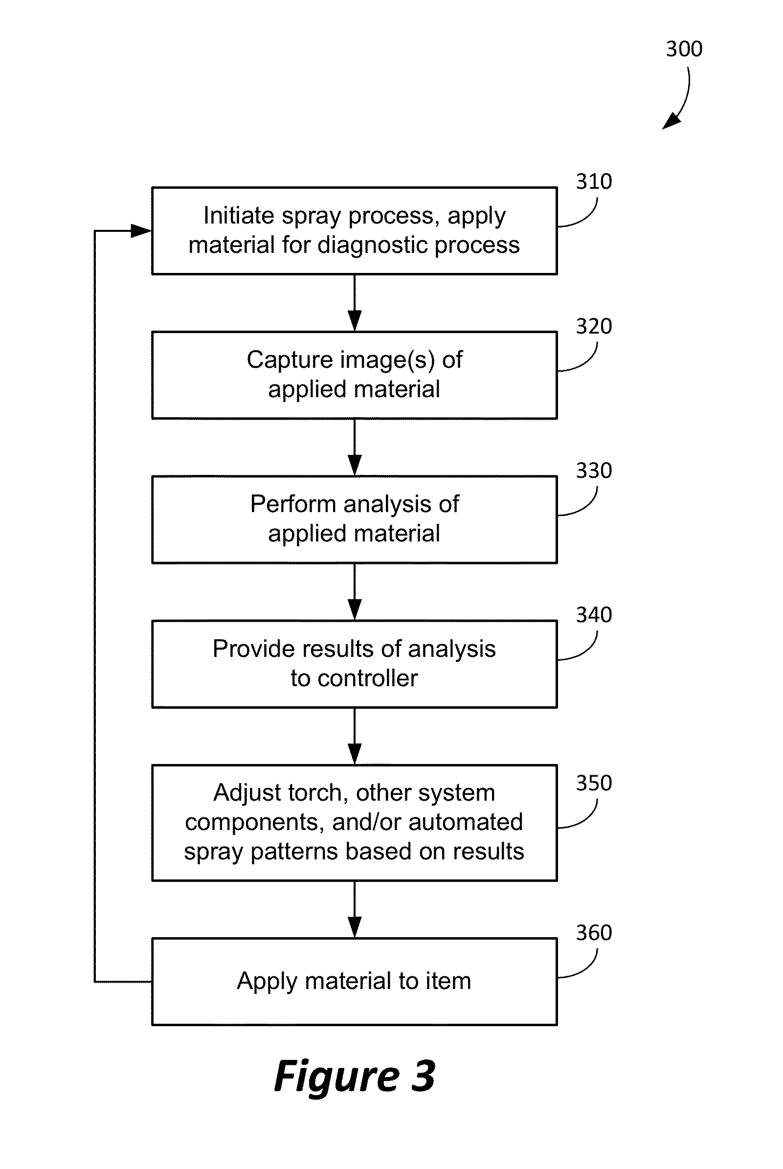
[0017]In an embodiment, process monitoring equipment may be integrated into a thermal spray system so that a spray plume position may be identified and characterized. Spray plume position data may be fed back into a robotic coating motion controller to align the p...


PUM

PropertyMeasurementUnit
widthaaaaaaaaaa
sizeaaaaaaaaaa
volumeaaaaaaaaaa

Abstract

A thermal spray system may include a thermal spray torch configured to produce an emission of material, at least one camera configured to capture an image of the emission of material emitted by the thermal spray torch, a diagnostic device communicatively coupled to the at least one camera, and a controller communicatively coupled to the diagnostic device. The camera may be configured to transmit an image of the emission of material to a diagnostic device that may be configured to determine a characteristic of the emission of material based on the image. The diagnostic device may transmit the characteristic to a controller that may control a position of the thermal spray torch based on the characteristic.

Description

TECHNICAL FIELD[0001]The present disclosure relates to coatings and in particular to methods and systems for using a combination of application techniques to apply coatings to articles.BACKGROUND[0002]Gas turbines, which may also be referred to as combustion turbines, are internal combustion engines that accelerate gases, forcing the gases into a combustion chamber where heat is added to increase the volume of the gases. The expanded gases are then directed towards a turbine to extract the energy generated by the expanded gases. Gas turbines have many practical applications, including use as jet engines and in industrial power generation systems.[0003]The accelerating and directing of gases within a gas turbine are often accomplished using rotating blades. Extraction of energy is typically accomplished by forcing expanded gases from the combustion chamber towards gas turbine blades that are spun by the force of the expanded gases exiting the gas turbine through the turbine blades. D...

Claims


Application Information

Patent Timeline
Patent Type & Authority Applications(United States)
IPC IPC(8): B05C11/02C23C16/52
CPCC23C4/129B05B12/082B05B13/0431B05B7/20B05D1/08
Inventor LOCHNER, CHRISTOPHER JOSEPHMARGOLIES, JOSHUA LEEDICKINSON, JON E.
Owner GENERAL ELECTRIC CO
Why Eureka
Try Eureka