
Cup type grinding wheel

Inactive Publication Date: 2013-12-12
GOEI
View PDF14 Cites 7 Cited by
  • Summary
  • Abstract
  • Description
  • Claims
  • Application Information

AI Technical Summary

Benefits of technology

The invention is about a lightweight coffee grinding wheel that can create a smooth and high-quality surface on the coffee beans. The technical effect of this invention is to improve the efficiency and precision of the coffee grinding process.

Problems solved by technology

However, a base plate to fix tips of the cup type grinding wheel in the patent documents 1 or 2 is heavy, because it is made of a metal such as aluminum or steel.
Therefore, there is a problem that a working load is great when a user operates a rotary tool equipped with the cup type grinding wheel attached thereto with one hand.
And, there is also a problem that power consumption in the rotary tool with the cup type grinding wheel is large, because the weight of the cup type grinding wheel is heavy.
Furthermore, as a metal base plate is poor in elasticity, the metal base plate cannot fully absorb vibrations or shocks generated while working such as grinding, cutting or tearing off a coating (each of these is named working hereinafter) is underway so that tips or pieces of grindstone on the grinding wheel do not keep uniform pressure on a work piece.
Therefore, the work piece is damaged or portions like wrinkles which are not machined in the work piece are generated because tips or pieces of grindstone do not abut on the portions.
Thus there is a problem that a poorly smoothed surface is made on a work piece.

Method used


Image

  • Cup type grinding wheel
  • Cup type grinding wheel
  • Cup type grinding wheel

Examples


example

[0087]The example of the grinding wheel according to the present invention will be explained in the following.

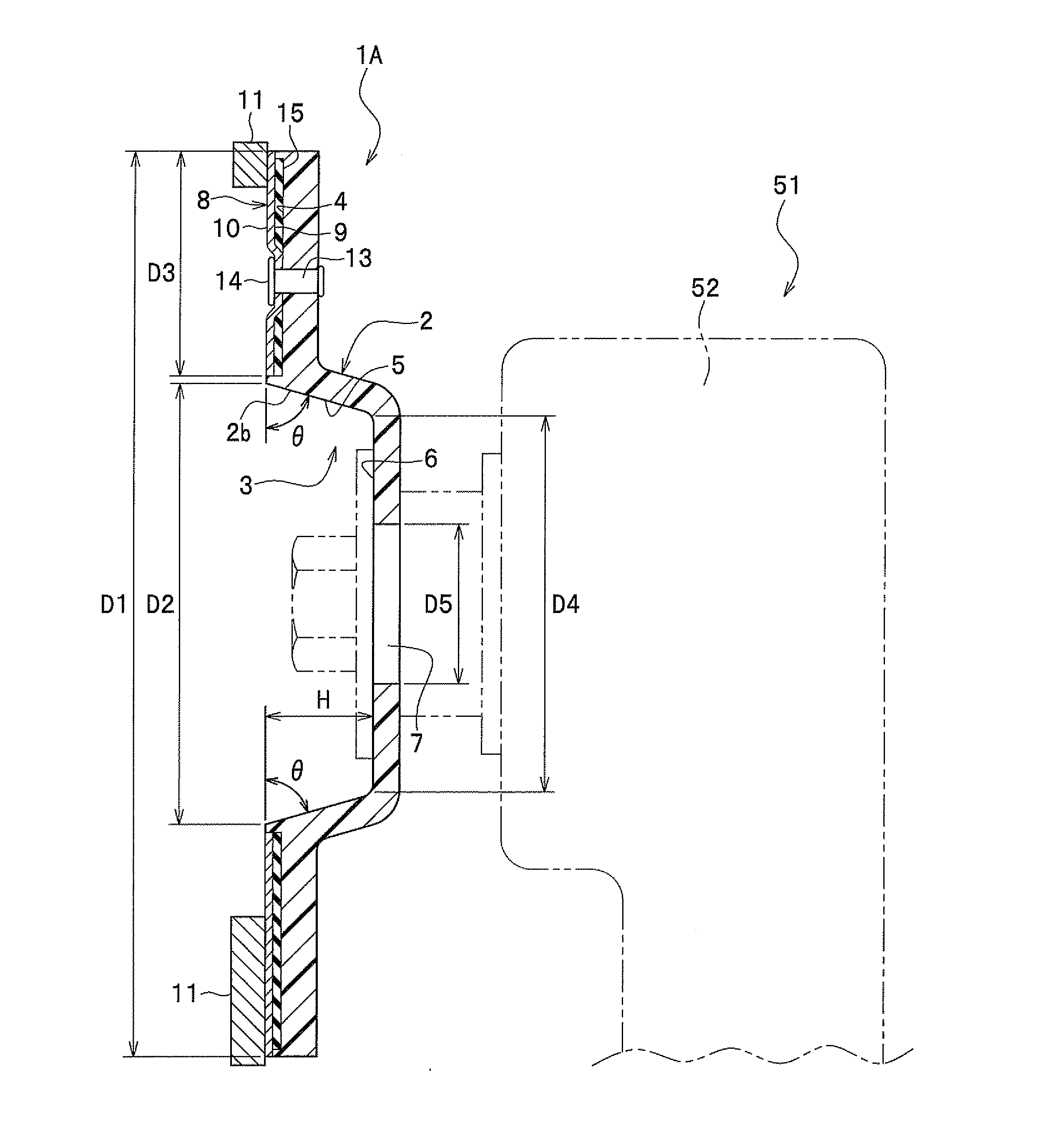
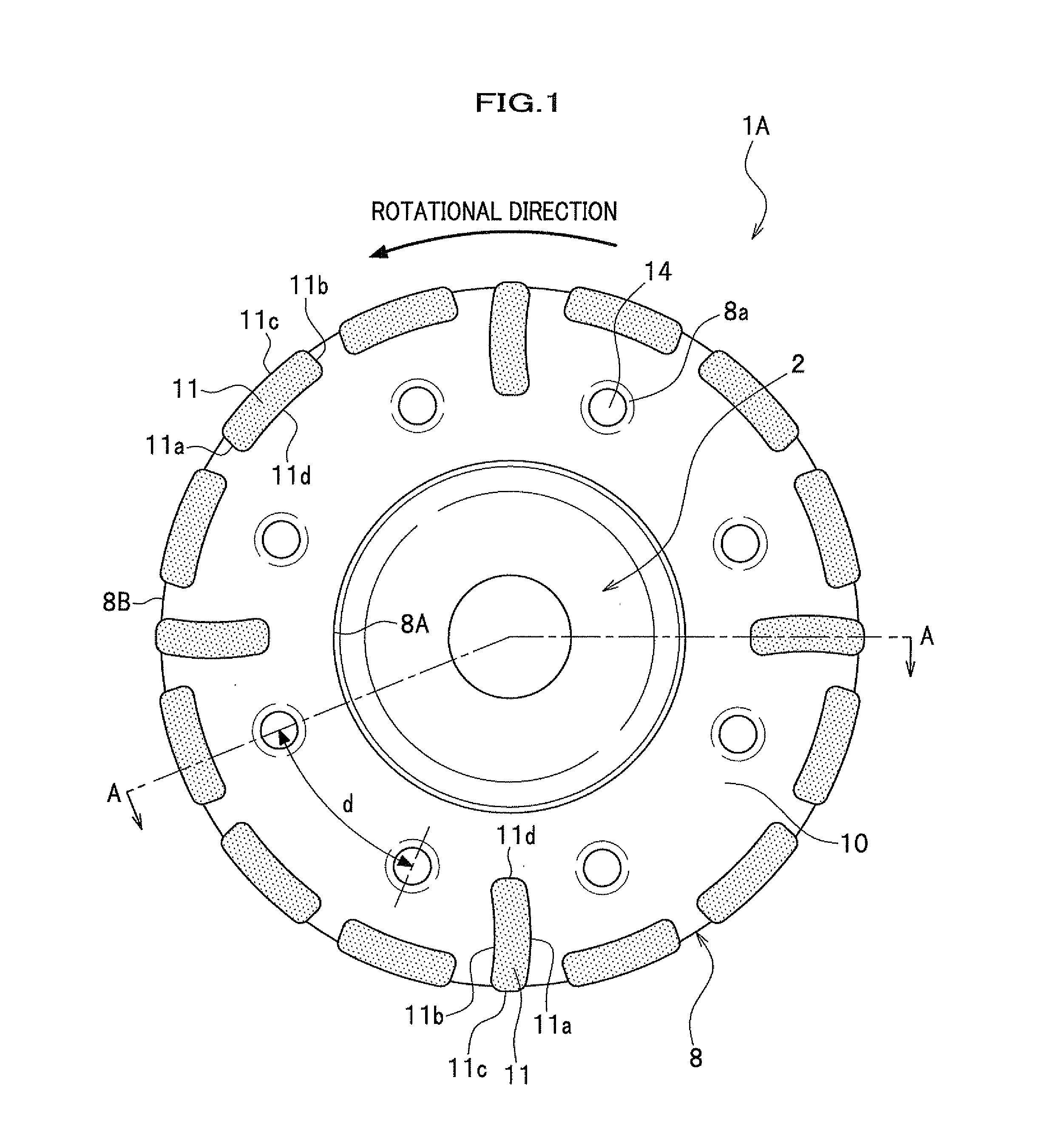
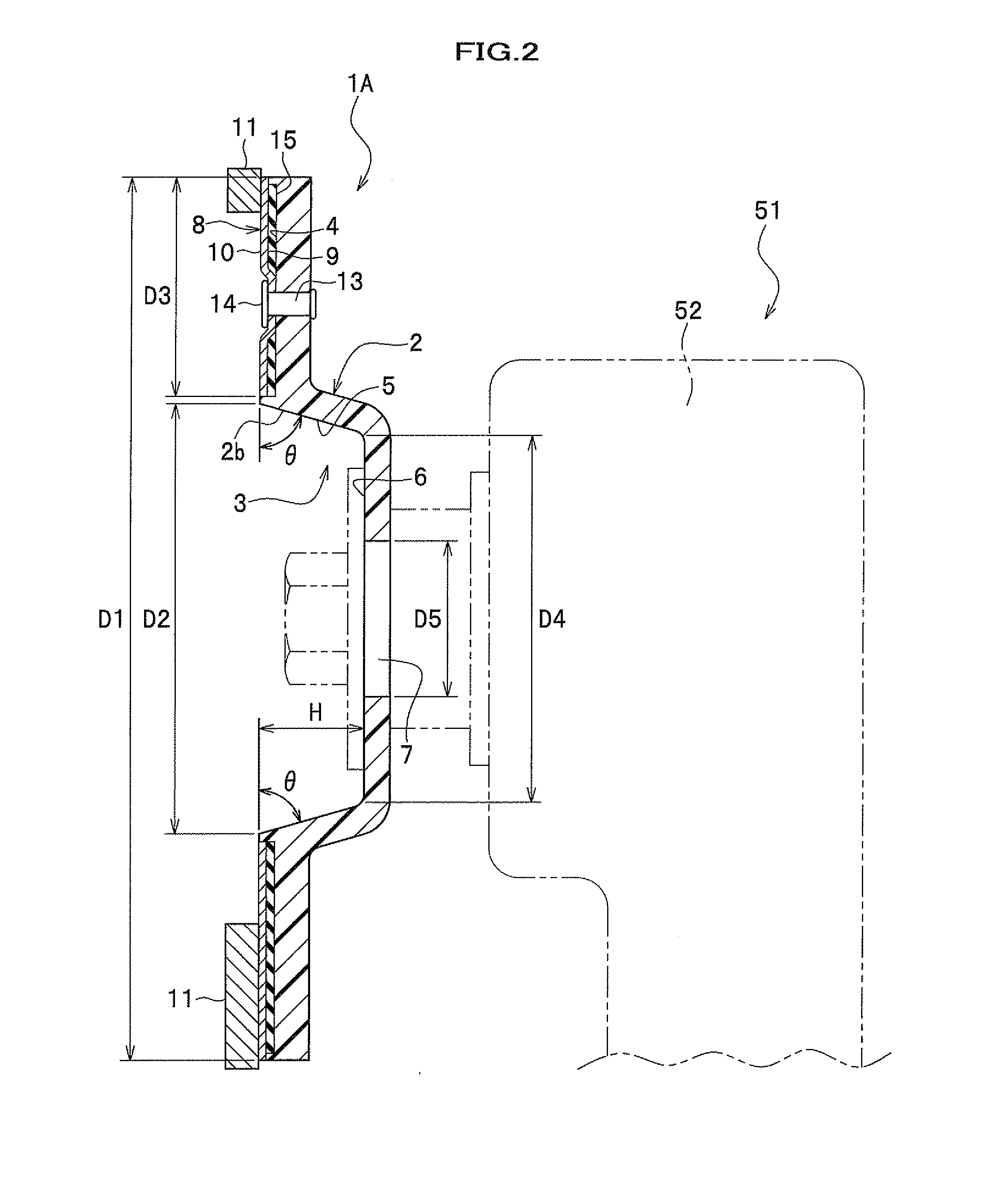
[0088]The grinding wheel as shown in FIGS. 1 and 2 is made by using the following members.

[0089](Plastic Base Plate)

[0090]A base plate made of a glass fiber-reinforced plastic (The brand name is TECAMID 66 GF 30) made by Ensinger Co., Ltd. whose outer diameter D1 is 123 mm, thickness is 3.5 mm, inner diameter D2 of the recessed portion 3 is 60 mm, height H of the recessed portion 3 is 13 mm, and the slant angle θ of the recessed portion 3 is 73 degrees is used.

[0091](Metal Annular Plate)

[0092]A metal annular plate made of SK5 (carbon tool steel) whose width is 30.5 mm and thickness is 1.0 mm is used.

[0093](Fastener)

[0094]A rivet made of stainless steel having a diameter of 4.0 mm is used.

[0095](Piece of Grindstone)

[0096]A piece of grindstone made of diamond abrasive grains whose size is 6 mm×20 mm×4.5 mm is used. Each piece of grindstone is fixed to the outer peripheral port...


PUM


Abstract

Cup type grinding wheel to be attached to a rotary tool includes a plastic base plate made of a glass fiber-reinforced plastic, a metal annular plate with pieces of grindstone or a ring-shaped grindstone on a fixing surface of the metal annular plate, and fasteners for integrating the plastic base plate with the metal annular plate. Heads of fasteners are positioned at the same level as the fixing surface or at a lower level than the fixing surface toward the plastic base plate.

Description

CROSS REFERENCE TO RELATED APPLICATIONS[0001]This application claims the foreign priority benefit under Title 35, United States Code, 119 (a)-(d) of Japanese Patent Application Nos. 2012-132377, 2012-170565 and 2013-50853 respectively filed on Jun. 11, 2012, Jul. 31, 2012 or Mar. 13, 2013 in the Japan Patent Office, each disclosure of which is herein incorporated by reference in each entirety.BACKGROUND OF THE INVENTION[0002]1. Technical Field[0003]The present invention relates to a cup type grinding wheel which is attached to a rotary tool such as a sander and for grinding a hard product like a concrete or ceramics-related thing, cutting it or tearing off coating of it and so on.[0004]2. Description of Background Art[0005]There are a flat type grinding wheel and a cup type grinding wheel in the prior art of a grinding wheel to be attached to a rotary tool. The former is a grinding wheel at an outer peripheral portion of a base plate like a circular plate of which tips like cutting ...

Claims


Application Information

Patent Timeline
IPC IPC(8): B24D7/06
CPCB24D7/066B24D7/06
Inventor KIMOTO, YUJITACHIBANA, KAZUMASA
Owner GOEI
Learn More