Thoracic diagnosis assistance information generation method, thoracic diagnosis assistance system, and dynamic state image processing apparatus

a technology of thoracic diagnosis and information generation method, which is applied in the field of thoracic diagnosis assistance information generation method, thoracic diagnosis assistance system, and dynamic image processing apparatus, can solve the problems of difficult detection and inability to see difference, and achieve the effect of easy recognition of ventilation diseas

Inactive Publication Date: 2013-12-12
KONICA MINOLTA INC
View PDF17 Cites 15 Cited by
  • Summary
  • Abstract
  • Description
  • Claims
  • Application Information

AI Technical Summary

Benefits of technology

[0037]According to the present invention, it is possible to generate diagnosis assistance information so that the physician can easily...

Problems solved by technology

However, among ventilation diseases of the lung, there are diseases where a difference cannot be seen between the inspiration air velocit...

Method used


Image

  • Thoracic diagnosis assistance information generation method, thoracic diagnosis assistance system, and dynamic state image processing apparatus
  • Thoracic diagnosis assistance information generation method, thoracic diagnosis assistance system, and dynamic state image processing apparatus
  • Thoracic diagnosis assistance information generation method, thoracic diagnosis assistance system, and dynamic state image processing apparatus

Examples


first embodiment

[Configuration of Thoracic Diagnosis Assistance System 100]

[0058]First, the configuration is described.

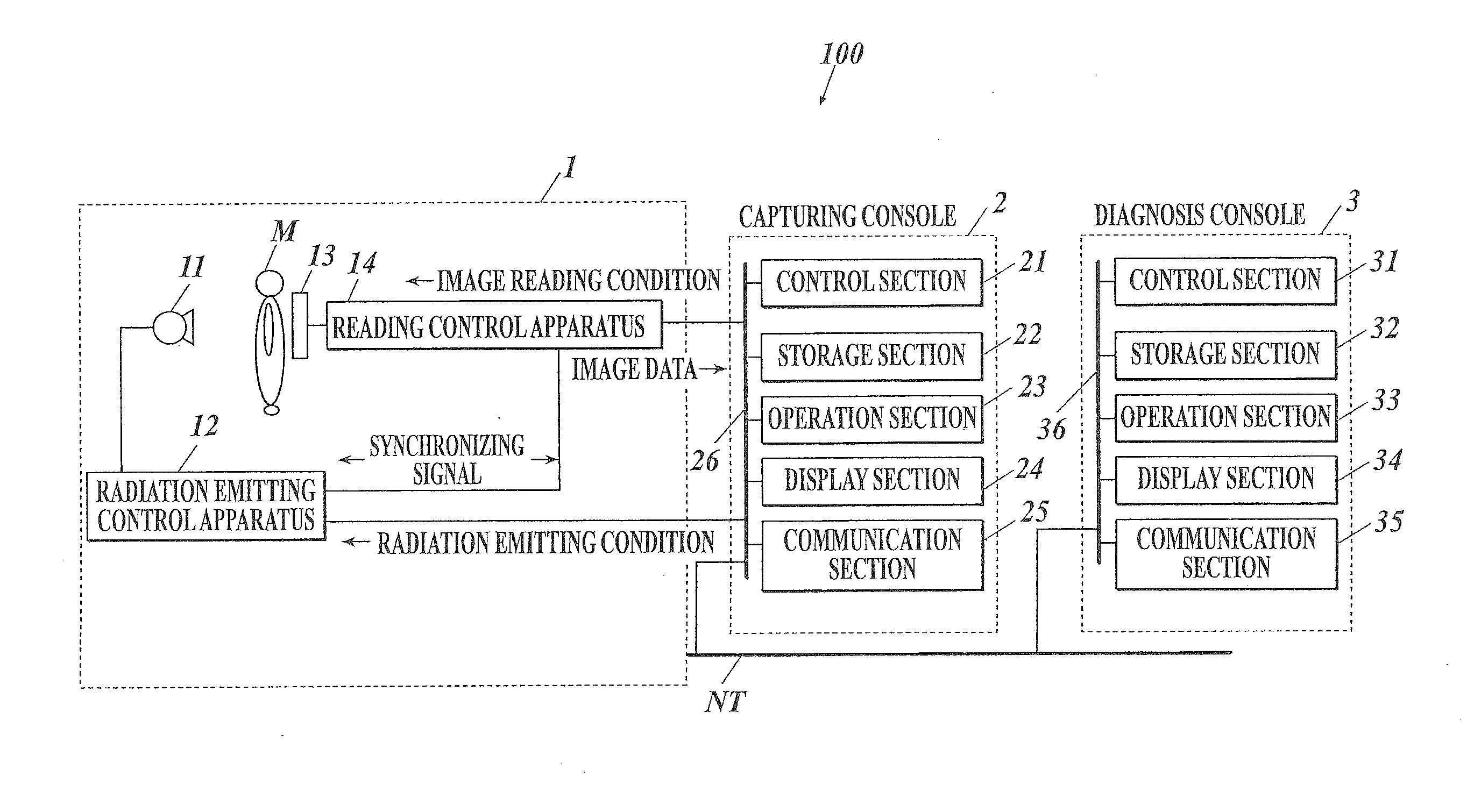
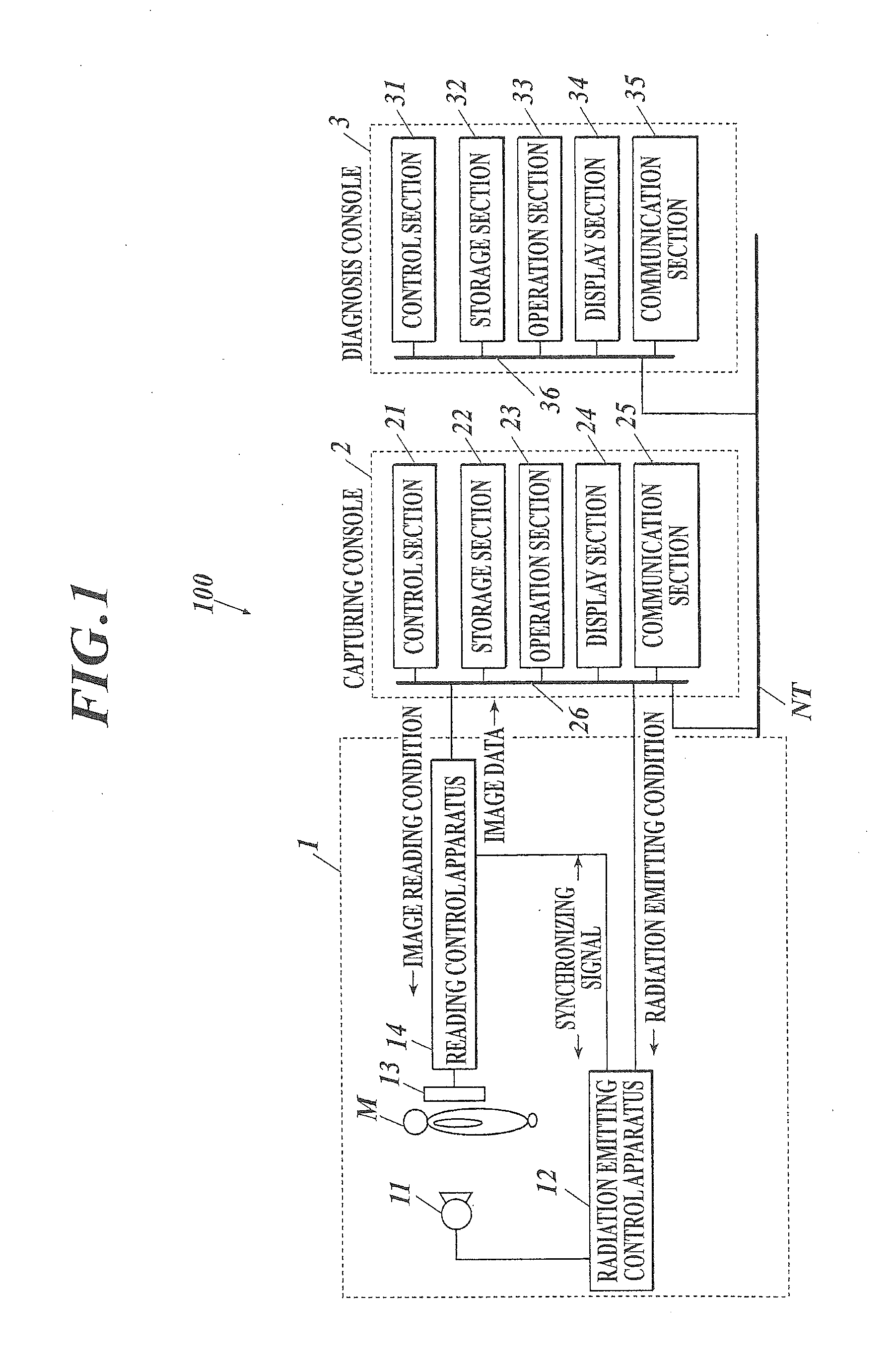
[0059]FIG. 1 shows an entire configuration of a thoracic diagnosis assistance system 100 of the present embodiment.

[0060]As shown in FIG. 1, the thoracic diagnosis assistance system 100 is configured by connecting a capturing apparatus 1 with a capturing console 2 through a communication cable, etc. and connecting a capturing console 2 with a diagnosis console 3 through a communication network NT such as a LAN (Local Area Network), etc. Each apparatus composing the thoracic diagnosis assistance system 100 complies to a DICOM (Digital Image and Communications in Medicine) standard, and communication between the apparatuses are performed according to DICOM.

[Configuration of Capturing Apparatus 1]

[0061]The capturing apparatus 1 is an apparatus to capture a state of the chest portion moving in cycles, such as change in shape from expansion and contraction of the lungs according to brea...

second embodiment

[0131]Next, the second embodiment is described.

[0132]The second embodiment is different from the first embodiment in that the template of the maximum air velocity distribution for each of expiration and inspiration of the normal lungs (normal air velocity distribution template) is stored in the storage section 32 of the diagnosis console 3. The content of the image analysis processing performed by the control section 31 of the diagnosis console 3 is also different. Other than the above, the entire configuration of the thoracic diagnosis assistance system 100, the configuration of each apparatus and the operation of the capturing apparatus 1 and the capturing console 2 are similar to those as described in the first embodiment and the description is to be referred.

[0133]The image analysis processing (image analysis processing B) of the second embodiment is described.

[0134]FIG. 9 shows a flowchart of image analysis processing B of the second embodiment. The image analysis processing B ...


PUM


Abstract

According to one implementation, a thoracic diagnosis assistance information generation method includes the following. A dynamic state of a chest portion is captured to generate frame images. Air velocity is calculated by dividing a lung field region extracted from one frame region into small regions, corresponding the small regions among the frame images, and calculating a feature amount showing air velocity. Air velocity distribution is calculated by dividing the lung field region into block regions in a trunk axis direction, calculating a feature amount showing air velocity of each block region based on a feature amount showing the air velocity of the small regions in the divided block regions, and calculating a feature amount showing air velocity distribution of the lung field region based on the calculated feature amount showing the air velocity of each block region.

Description

CROSS REFERENCE TO RELATED APPLICATIONS[0001]The present application claims priority under 35 U.S.C. §119 to Japanese Application No. 2012-131594 filed on Jun. 11, 2012, the entire content of which is incorporated herein by reference.BACKGROUND[0002]1. Field of the Invention[0003]The present invention relates to a thoracic diagnosis assistance information generation method, a thoracic diagnosis assistance system, and a dynamic image processing apparatus.[0004]2. Description of Related Art[0005]Instead of stationary image capturing and diagnosis by thoracic radiation using a conventional film / screen or photostimulable phosphor plate, there is an approach to capture a thoracic dynamic image using a semiconductor image sensor such as an FPD (flat panel detector), etc., to be applied to diagnosis.[0006]Specifically, fast responsiveness of reading and deleting of image data of the semiconductor image sensor is used and pulsed radiation is successively emitted from a radiation source to m...

Claims


Application Information

Patent Timeline
IPC IPC(8): A61B6/00A61B5/087
CPCA61B6/5217A61B5/087A61B6/5288G06T7/0016G06T2207/10016G06T2207/10116G06T2207/30061
Inventor NOJI, SHOMURAOKA, SHINTARO
Owner KONICA MINOLTA INC
Why Eureka
Try Eureka