Controlling method and system for compressed air supply to a pneumatic network, in particular in an aircraft

Active Publication Date: 2013-12-19
SAFRAN POWER UNITS
View PDF2 Cites 28 Cited by
  • Summary
  • Abstract
  • Description
  • Claims
  • Application Information

AI Technical Summary

Benefits of technology

[0011]The invention aims at overcoming such major disadvantage by basing the management of the tapped air flow rate variations

Problems solved by technology

Moreover, in general, the APU unit only supplies such pneumatic power on ground.
However, such management solution for air flow rate variations needs an oversizing of the load compres

Method used


Image

  • Controlling method and system for compressed air supply to a pneumatic network, in particular in an aircraft
  • Controlling method and system for compressed air supply to a pneumatic network, in particular in an aircraft

Examples


Embodiment Construction

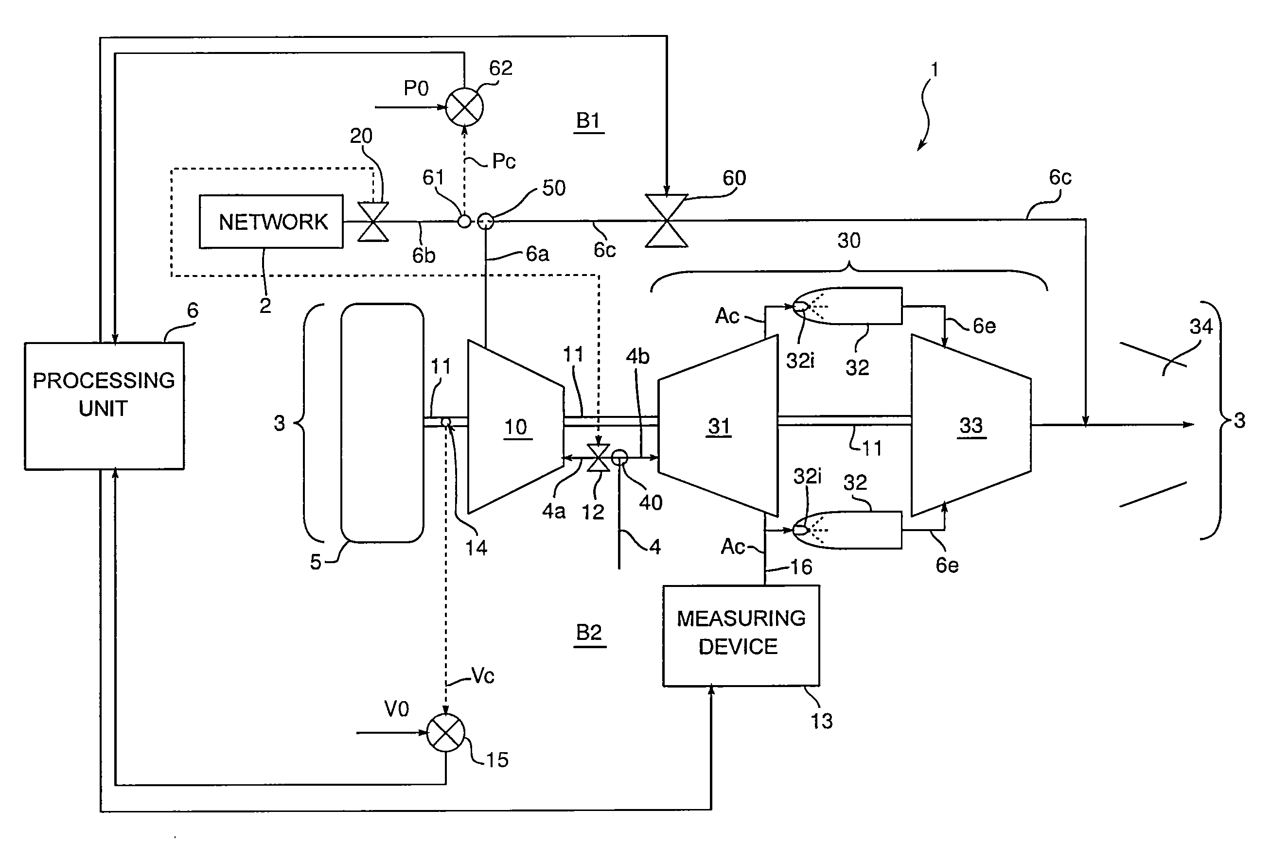
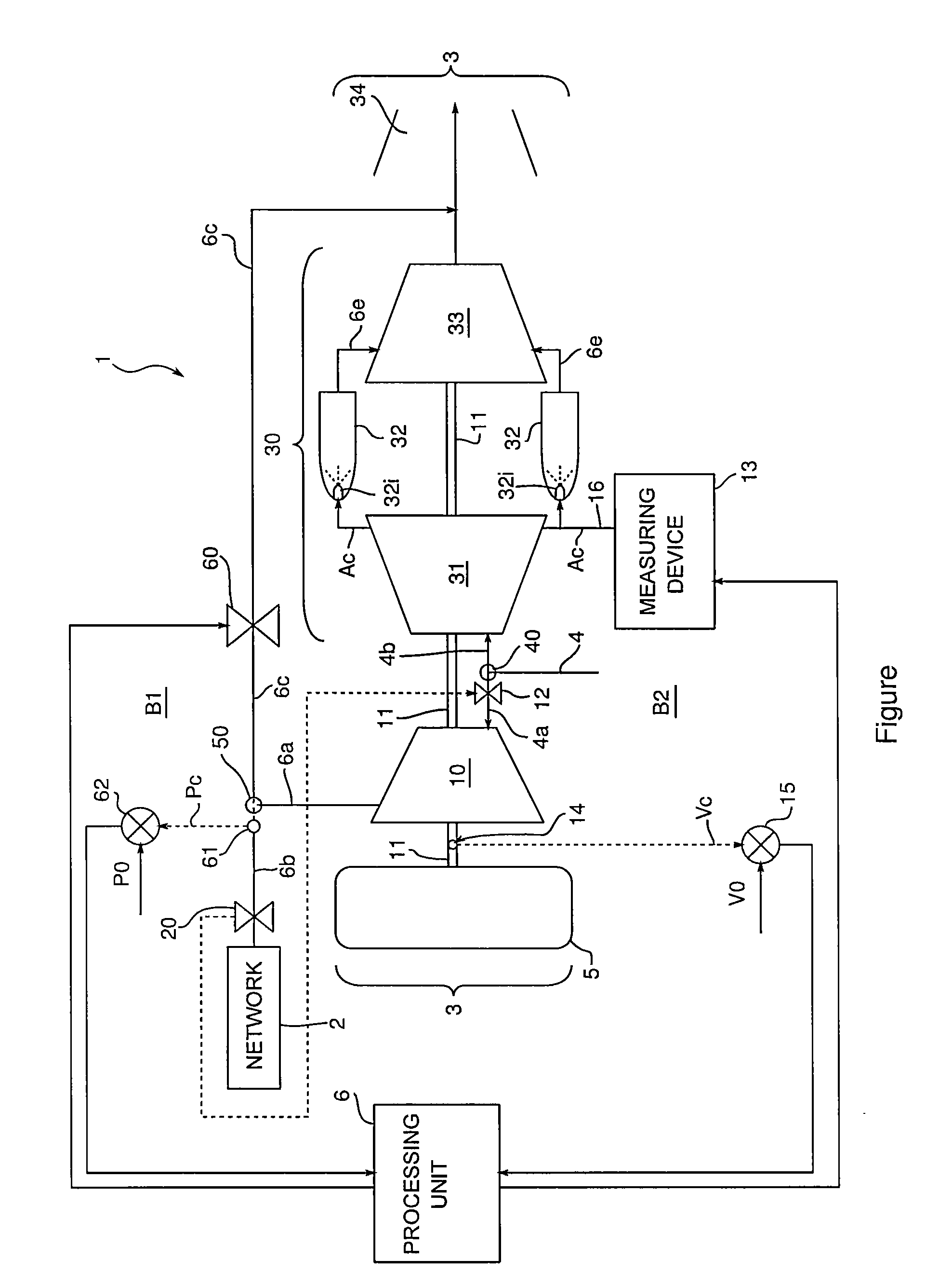
[0026]Referring to the schema of the unique figure, the exemplary base architecture for a compressed air supply system 1 to a pneumatic network of an aircraft comprises a load compressor 10 being driven by the power shaft 11 of an APU unit 3 of an aircraft. An APU unit is applied on ground or sometimes in flight for a non propulsive energy supply. In particular on a descent phase, extra pneumatic energy can be necessary so as to provide an efficient de-icing of the airplane or to release the main engines from non propulsive functions.

[0027]Such an APU unit 3 essentially consists in a gas generator 30—coupling a main compressor 31, a combustion chamber 32 and a power turbine 33—and a gas ejection nozzle 34 in post-combustion.

[0028]An air supply 4 provides air to the main compressor 31 and the load compressor 10 via IGV valves 12. To do so, the supply 4 is respectively divided into two conducts 4a and 4b through a T-shaped connection 40. The compressor 31 supplies the injectors 32i of...


PUM


Abstract

A system for supplying compressed air to a pneumatic network includes a load compressor, an air supply and a power shaft driving the load compressor. The system also includes in an air outlet of such load compressor, a connecting channel connected, on the one side, with a channel connected with the pneumatic network and, on the other side, with an air discharge conduct towards an exhaust nozzle. Air flow rate bleed valves are controlled by a processing unit via servo-loops as a function of the pressure sensors and the speed sensor.

Description

TECHNICAL FIELD[0001]The present invention relates to a controlling method for compressed air supply to a pneumatic network, in particular for the network of an aircraft—including, but not exclusively from an auxiliary power unit, in short APU (Auxiliary Power Unit) equipping in general the aircraft—as well as a controlling system for the implementation thereof.[0002]The invention applies to aircrafts, i.e. to airplanes (commercial airplanes, regional airplanes or small jet type airplanes) as well as to helicopters. The invention can use a drive through the APU unit equipping the aircraft, but also a piston engine or an electrical engine.[0003]The aircrafts are provided with a motorization comprising main engines—dedicated to the propulsion and, in a cruising rating, to the generation of a non propulsive energy from energy consuming equipment (pneumatic, mechanical, hydraulic, electricity, etc.)—as well as an APU unit in general.[0004]An APU unit is a small turbo-engine or auxiliary...

Claims


Application Information

Patent Timeline
IPC IPC(8): F15B15/00
CPCF15B15/00F05D2270/3015B64D41/00F01D17/06F01D17/08F01D17/16F02C6/06F02C9/26F05D2220/50F05D2270/304F04D27/0215F05B2220/60F02C9/28F02C7/32F04D27/0207F04D27/0223F02C9/18F04D27/02F02C6/08F01D17/105F01D17/00F04D27/023
Inventor SILET, FABIENCHEVALIER, STEPHANERIDEAU, JEAN-FRANCOIS
Owner SAFRAN POWER UNITS
Why Eureka
Try Eureka