Lubricating device for power unit

a technology for lubricating devices and power units, which is applied in the direction of mechanical equipment, machines/engines, gearing details, etc., can solve the problems of difficult oil feeding to the oil reservoir, and achieve the effects of reducing the starting load, reducing the increase in the load of the scavenging pump, and simplifying construction

Active Publication Date: 2013-12-19
HONDA MOTOR CO LTD
View PDF5 Cites 16 Cited by
  • Summary
  • Abstract
  • Description
  • Claims
  • Application Information

AI Technical Summary

Benefits of technology

[0013]According to the first feature, the oil reservoir for storing a certain amount of oil to immerse the lower part of the clutch is provided in the power unit case, and the first overflow passage is provided in the oil tank such that when the stored oil in the oil tank is increased beyond the first level, the first overflow passage allows the increased oil to overflow into the oil reservoir side. Therefore, during the operation of the engine, the surplus oil which overflows from the oil tank is stored a certain amount in the oil reservoir, and the lower part of the clutch can be immersed in the stored oil of the oil reservoir, so that, during the operation of the engine the cooling and lubrication of the clutch can be always ensured, and a power loss due to the oil stirring by a starting clutch can be controlled to the most possible extent.
[0014]According to the second feature, the outlet passage is provided in the bottom portion of the oil reservoir for allowing the oil to flow from the oil reservoir to the oil pan side such that an outflow amount of the oil passing the outlet passage is less than an outflow amount of the oil flowing from the oil tank to the oil reservoir side. Therefore, at the time of the operation of the engine, when the operation of the scavenging pump and the feed pump stops, the overflow of the oil from the oil tank to the oil reservoir side stops. On the other hand, the stored oil in the oil reservoir flows out through the outlet passage to the oil pan, whereby it is possible to empty the oil reservoir after a lapse of a predetermined time. Accordingly, when starting the engine again, since the oil reservoir is in an empty condition, the oil stirring due to the rotation of the clutch does not occur, thereby reducing the starting load, so that the engine starting can be smoothly performed.
[0015]According to the third feature, the second overflow passage is provided in the oil tank such that when the stored oil in the oil tank is increased beyond the second level which is higher than the first level, the second overflow passage allows the increased oil to overflow into the oil pan, and the flow passage resistance of the second overflow passage is set smaller than that of the first overflow passage. Therefore, after the oil tank is filled with the oil discharged from the scavenging pump, the surplus oil is allowed to overflow from the second overflow passage to the oil pan, whereby the increase in load of the scavenging pump can be restrained.
[0016]According to the fourth feature, the power unit case is divided into the case cover for covering the clutch and the case block adjacent to the case cover, wherein the oil tank and the oil reservoir are formed between the joining faces of the case cover and the case block. Therefore, there is no need for provision of a special oil tank and a special oil reservoir separate from the power unit case, whereby the power unit can be simplified in construction and lightened in weight.
[0017]According to the fifth feature, the oil filler hole which is open to the oil tank above the lower edge of the second overflow passage and is normally closed by the filler cap is provided on the upper part of the oil tank. Therefore, when the oil has been poured from the oil filler hole of the oil tank, firstly the oil fills the oil tank. Thereafter, when the oil within the oil tank is increased beyond the first and the second levels, the increased oil overflows through the first and second overflow passages so as to be stored finally in the oil pan. Accordingly, the oil feed of a predetermined amount to the oil tank and the oil pan can be preformed rapidly by the oil feeding from the single oil filler hole, and the oil feeding operation can be facilitated.
[0018]According to the sixth feature, the oil strainer having an internal part of the oil tank partitioned into the upper chamber and the lower chamber is arranged within the oil tank, wherein the oil filler hole, the first overflow passage and the second overflow passage are opened into the upper chamber, and wherein the first overflow passage and the second overflow passage are offset with respect to the oil filler hole in a plan view from above. Therefore, at the time of the oil feeding through the oil filler hole, the oil fills the oil tank firstly and, thereafter, overflows through the first and second overflow passages so as to be stored in the oil pan. Accordingly, when monitoring an oil level of the oil within the oil pan with an oil gauge, excessive feed to the oil pan can be prevented. Moreover, the oil filling the oil tank can be filtrated by the oil strainer.

Problems solved by technology

In the lubricating device of this type, variations exist in the amount of oil splashed up by the crank weight, depending upon operating conditions of the engine, so that there may be cases where the stable oil feeding to the oil reservoir becomes difficult.

Method used


Image

  • Lubricating device for power unit
  • Lubricating device for power unit
  • Lubricating device for power unit

Examples


Embodiment Construction

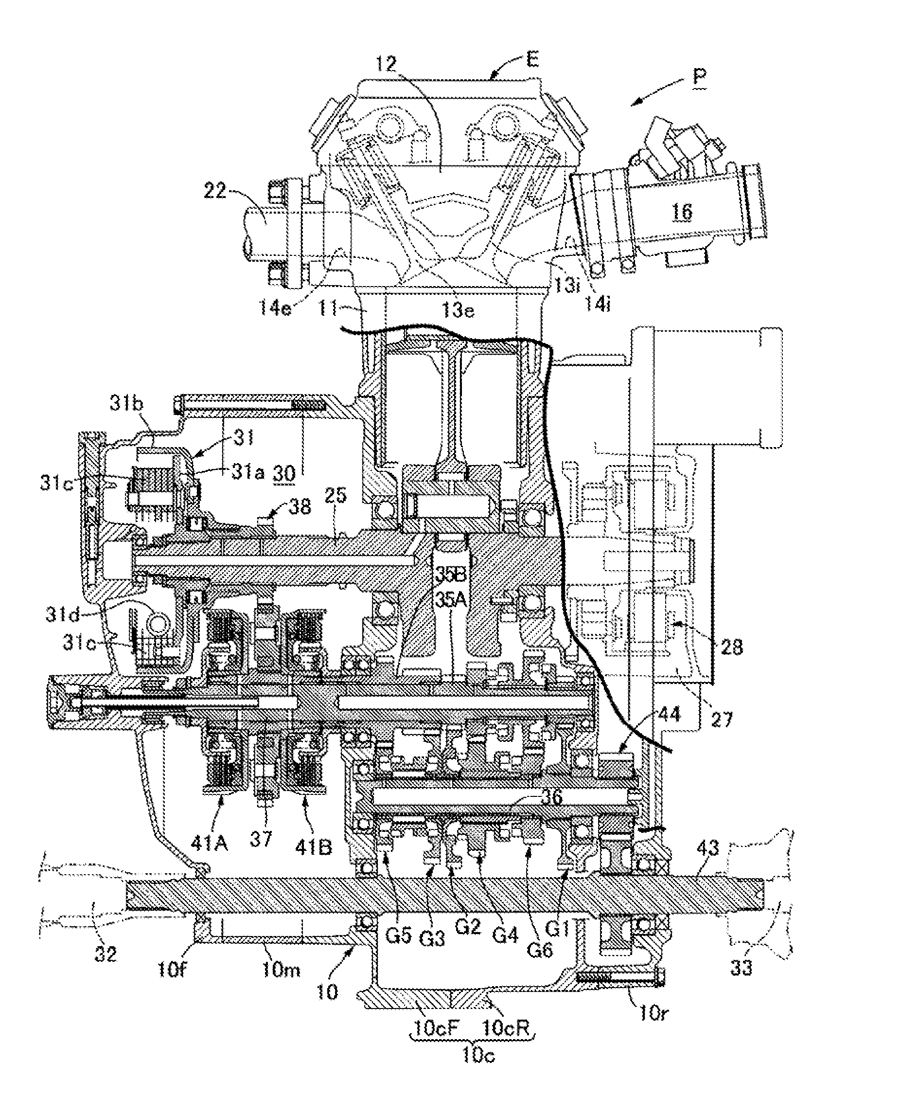
[0027]Hereinafter, the embodiment applying the present invention to a straddle type four-wheeled all-terrain vehicle will be described with reference to accompanying drawings. In the description hereunder, “front”, “rear”, “left” and “right” are referred to in accordance with the orientation of the straddle type four-wheeled all-terrain vehicle.

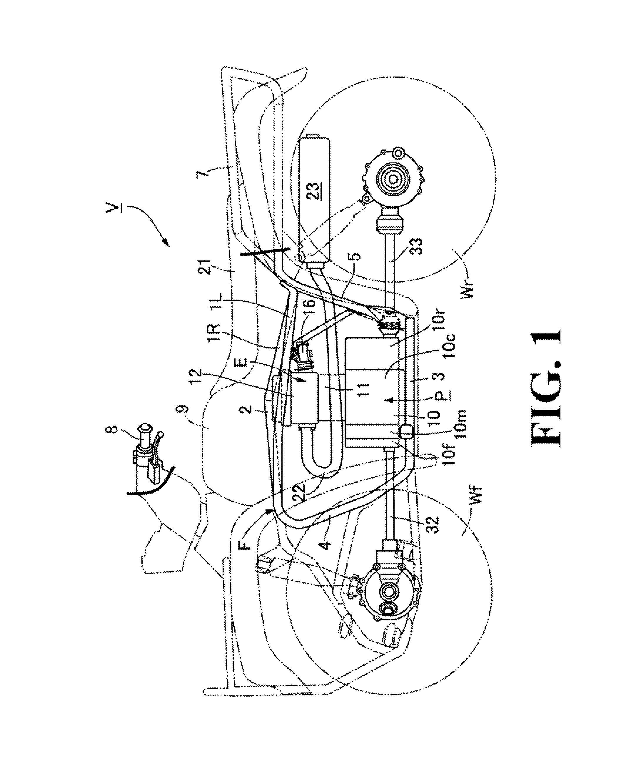
[0028]First in FIG. 1, a vehicle body frame F of the straddle type four-wheeled all-terrain vehicle B comprises a pair of left and right main frames 1L, 1R having an upper side frame 2, a lower side frame 3, a front side frame 4 and a rear side frame 5 combined into a quadrilateral shape, a plurality of cross members (not shown) establishing an integral connection between the left and right main frames 1L, 1R, and a seat rail 7 connected to rear portions of the upper side frames 2 of each of the main frames 1L, 1R. From front and rear portions of the left and right main frames 1L, 1R there are suspended a pair of left and right front wheels W...


PUM


Abstract

A lubricating device for a power unit includes an oil pan, an oil tank being separated from the oil pan, a scavenging pump for circulating the received oil of the oil pan to the oil tank, and a feed pump to feeding oil stored in the oil tank to the engine and the transmission, wherein an oil reservoir for storing a certain amount of oil to immerse a lower part of a clutch that connects and disconnects a transmission route between the engine and the transmission is provided in a power unit case, and a first overflow passage is provided in the oil tank such that when the stored oil in the oil tank is increased beyond a first level, the first overflow passage allows the increased oil to overflow into the oil reservoir side.

Description

CROSS-REFERENCE TO RELATED APPLICATIONS[0001]The present application claims priority under 35 U.S.C. §119 to Japanese Patent Application No. 2012-134494, filed Jun. 14, 2012, the contents of which is incorporated herein, by reference, in its entirety.TECHNICAL FIELD[0002]The present invention relates to a lubricating device for a power unit, which comprises an oil pan for receiving oil that has lubricated an engine and a transmission, an oil tank separated from the oil pan, a scavenging pump for circulating or returning the received oil of the oil pan to the oil tank, and a feed pump for feeding the stored oil in the oil tank to the engine and the transmission, and more particularly, to the lubricating device configured to use the lubricating oil of the power unit to perform the cooling of a clutch that connects and disconnects the transmission route between the engine and the transmission.BACKGROUND OF THE INVENTION[0003]A lubricating device for a power unit has already been known ...

Claims


Application Information

Patent Timeline
Patent Type & Authority Applications(United States)
IPC IPC(8): F01M1/02F16H57/04
CPCF01M1/02F01M11/0004F16H57/045F01M2001/123F01M2011/0095F16H57/0447F16H57/0475F16H57/0473
Inventor TSUNASHIMA, KOUSUKETAKI, MASAFUMIHAMAOKA, SEIJIHIRAYAMA, TAKU
Owner HONDA MOTOR CO LTD
Why Eureka
Try Eureka