Method for coating turbomachine guide vane and associated guide vane

A turbine engine and blade technology, which is applied in the coating field of turbine engine guide vanes, can solve problems such as large aerodynamic loss, and achieve the effect of improving aerodynamic performance

Active Publication Date: 2022-02-01
SAFRAN AIRCRAFT ENGINES SAS
View PDF5 Cites 0 Cited by
  • Summary
  • Abstract
  • Description
  • Claims
  • Application Information

AI Technical Summary

Problems solved by technology

In addition, grooves can generate considerable aerodynamic losses if they involve unbonded confining layers or more generally undirected chaotic flow

Method used


Image

  • Method for coating turbomachine guide vane and associated guide vane
  • Method for coating turbomachine guide vane and associated guide vane
  • Method for coating turbomachine guide vane and associated guide vane

Examples


Embodiment Construction

[0041] The drawings are for illustrative purposes and do not limit the invention in any way.

[0042] Unless otherwise stated, identical elements appearing in different figures have a single reference number.

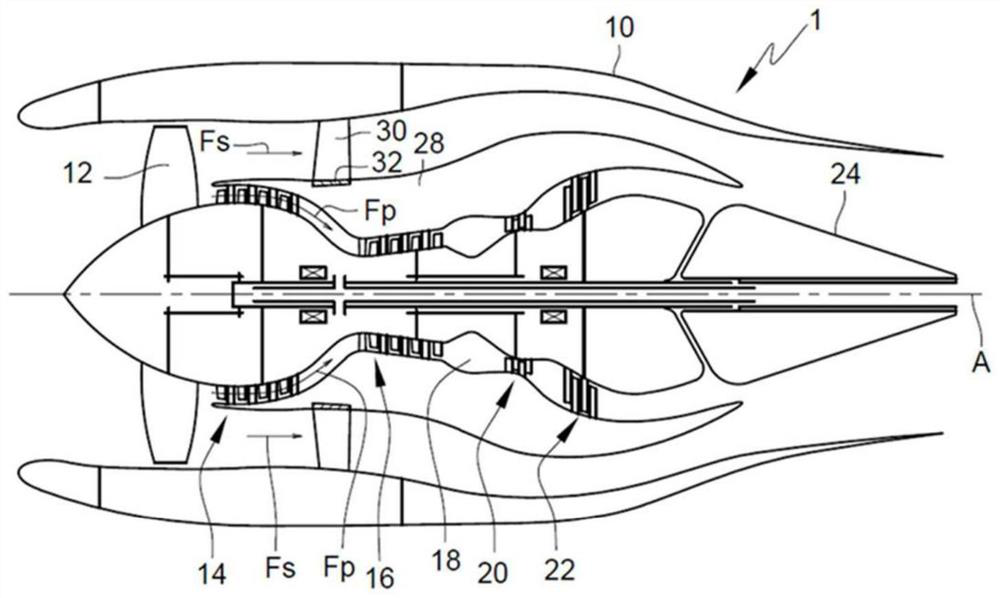
[0043] figure 1 A schematic view of the longitudinal interface of the bypass turbine engine 1 is shown.

[0044] In the remainder of the present description, the terms “inner” and “outer”, “axial” and “radial” and their derivatives are defined relative to the longitudinal axis A of the turbine engine 1 .

[0045] refer to figure 1 , the bypass turbine engine 1 has a longitudinal axis A and includes a casing 10, in which a fan 12, a low-pressure compressor 14, a high-pressure compressor 16, a combustion chamber 18, a high-pressure turbine 20, a low-pressure turbine are arranged from upstream to downstream. 22 and exhaust cone 24. An inner casing 28 is disposed within the outer casing 10 surrounding the compressors 14 and 16 and the turbines 20 and 22 of the combustor...


PUM


Abstract

One aspect of the invention relates to a method (200) for coating a vane (100) of a guide vanes assembly (30) of a turbomachine (1), the vane comprising a root (103) and a tip (104), an extrados face (105) and an intrados face (106) which are connected to one another by a leading edge (101) and a trailing edge (102), the coating method (200) comprising the following steps: completely covering (201) one of the faces (105, 106) of the vane (100) with a polymer coating (107) of thickness (e1) and provided with grooves (108), removing (203) the grooves (108) from part of the polymer coating (107) so that the polymer coating (107) comprises a grooved zone (109) and an ungrooved zone (110), coating (205) the grooved zone (110) with a coat of paint (111) of thickness (e3) so that the thickness of the coat of paint (111) superposed with the grooved zone (110) is substantially equal to the thickness (e1) of the grooved zone (109).

Description

technical field [0001] The present invention relates generally to the field of turbine engines. [0002] The invention relates more particularly to a method of coating turbine engine guide vanes making it possible to optimize the aerodynamic performance of said guide vanes. The invention also relates to a coated guide vane. Background technique [0003] The bypass turbine engine includes at its upstream end an air intake that supplies air to a fan that splits the annular airflow into two airflows. [0004] A portion of the airflow, called the primary flow, is injected into the compressor, which powers the turbine that drives the fan. Another part of the airflow, called the secondary flow, is injected into the atmosphere after passing through a ring of fixed blades downstream of the fan to provide a portion of the turbine engine's thrust. [0005] Fixed blade rings, also known by abbreviation as OGV (Outlet Guide Vanes), enable the airflow at the fan outlet to be directed ...

Claims


Application Information

Patent Timeline
Patent Type & Authority Applications(China)
IPC IPC(8): F01D5/28F01D9/04
CPCF01D5/282F01D9/041F05D2250/11F01D5/288F05D2230/31F05D2230/90F05D2240/121F05D2240/122
Inventor 西莉亚·伊格莱西亚斯·卡诺文森特·玛丽·雅克·雷米·德·卡内-卡纳瓦莱安托万·休伯特·玛丽·让·马森
Owner SAFRAN AIRCRAFT ENGINES SAS
Why Eureka
Try Eureka