
Pv power converter

A power converter and power conversion technology, applied in the output power conversion device, the conversion of DC power input to DC power output, and the conversion of AC power input to DC power output, etc., can solve the damage of cable insulation and prevent DC fault current from extinguishing. arc and other problems, to achieve the effect of low power loss

Pending Publication Date: 2021-09-21
ABB (SCHWEIZ) AG
View PDF5 Cites 0 Cited by
  • Summary
  • Abstract
  • Description
  • Claims
  • Application Information

AI Technical Summary

Problems solved by technology

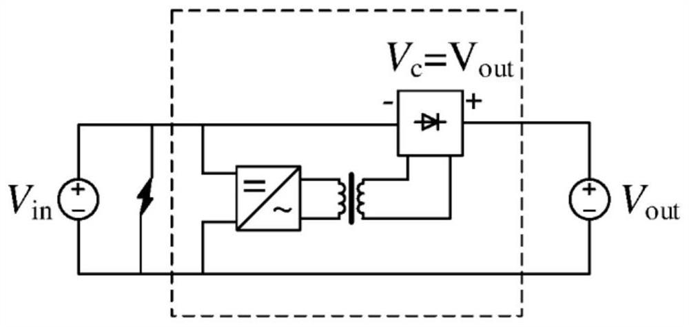
[0006] Although PPC provides high system efficiency, it has disadvantages during input DC bus short-circuit fault: when input DC bus short-circuit fault occurs, such as Figure 2A shown, the rectifier will have to withstand the voltage V out , that is, V c =V out , where V c is the voltage at the rectifier
Although the fault current injected from the DC input side (PV panel) is not high, it hinders the arc extinguishing of the DC fault current, which may cause additional damage to the cable insulation of the output DC bus

Method used


Image

  • Pv power converter
  • Pv power converter
  • Pv power converter

Examples


Embodiment Construction

[0023] In the following description, for purposes of explanation and not limitation, specific details are set forth, such as particular circuits, circuit components, interfaces, techniques, etc., in order to provide a thorough understanding of the present invention. It will be apparent, however, to one skilled in the art that the present invention may be practiced in other embodiments that depart from these specific details. In other instances, detailed descriptions of well-known methods and procedures, devices, and circuits are omitted so as not to obscure the description of the present invention with unnecessary detail.

[0024] While the invention is susceptible to various modifications and alternative forms, specific embodiments thereof are shown by way of example in the drawings and will be described in detail herein. It should be understood, however, that the drawings and detailed description thereof are not intended to limit the invention to the particular form disclose...


PUM


Abstract

It provides a PV power converter (2) including: a transformer (23), a first output port (Pout1) and a second output port (Pout2), a first power conversion circuit (24) being configured to convert power from PV array (20) into AC power. The first power conversion circuit (24) has a first input terminal (Tin1) and a second input terminal (Tin2) being configured to be electrically coupled to outputs of PV array (20) with the second input terminal (Tin2) electrically coupled to the second output port (Pout2); and a first output terminal (Tout1) and a second output terminal (Tout2) electrically coupled to a primary winding (23p) of the transformer (23). The PV power converter (2) also includes a second power conversion circuit (25) being configured to convert power from the transformer (23) into DC power. The second power conversion circuit (25) has a first input end (E in1) and a second input end (E in2) electrically coupled to a secondary winding (23s) of the transformer (23), and a first output end (E out1) electrically coupled to the first output port (P out1) and a second output end (Eout2 ) electrically coupled to the first input terminal (Tin1) of the first power conversion circuit (24). The PV power converter (2) also includes a first power switch (Q 1) being arranged electrically between either of the first input terminal (Tin1) and the second input terminal (Tin2) and either of the first output port (Pout1) and the second output port (Pout2), having a conducting direction allowing unidirectional current flow.

Description

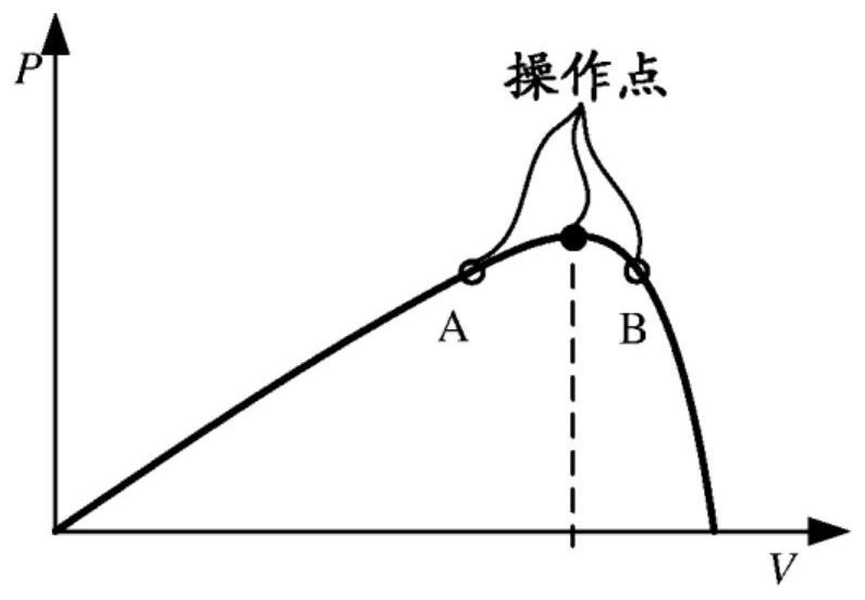
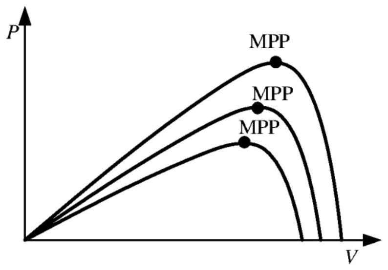
technical field [0001] The present invention relates generally to PV (photovoltaic) power conversion, and more particularly to protection against faults in PV power conversion equipment. Background technique [0002] Photovoltaic systems are very popular as a renewable energy source in many applications. PV modules of photovoltaic systems have a maximum power point (MPP) phenomenon, ie a PV module outputs maximum power at a certain point that is not the end of the operating range. In addition, the output power of PV modules will vary with temperature and irradiance. Figure 1A is the P-V curve of the PV module showing the MPP phenomenon. Such as Figure 1A As shown, in region A, in the direction towards the MPP, the output power of the PV module increases with the increase of the output voltage of the PV module. On the contrary, in the region B, in the direction away from the MPP, the output power of the PV module decreases with the increase of the output voltage of the PV...

Claims


Application Information

Patent Timeline
Patent Type & Authority Applications(China)
IPC IPC(8): H02M7/5387H02J3/32H02H7/18
CPCY02E10/56H02M3/33573H02M1/0093H02J3/381H02J2300/26H02M1/32
Inventor 杨晓波刘卓然黄杏
Owner ABB (SCHWEIZ) AG
Learn More