Vibrating body, method of manufacturing the same and vibration type drive device

a technology of vibration type drive and vibrating body, which is applied in the direction of piezoelectric/electrostrictive/magnetostrictive devices, piezoelectric/electrostriction/magnetostriction machines, coatings, etc., can solve the problems of reducing the efficiency of the vibration type drive device, and adversely affecting the performance of the small vibration type drive device. , to achieve the effect of reducing

Active Publication Date: 2013-12-19
CANON KK
View PDF5 Cites 20 Cited by
  • Summary
  • Abstract
  • Description
  • Claims
  • Application Information

AI Technical Summary

Benefits of technology

[0015]In the vibrating body 21 of a known vibration type drive device described above by referring to FIG. 8, the multilayered piezoelectric element 23 and the vibrating plate (to be referred to as substrate hereinafter) 22 that is made of metal are bonded to each other by means of an adhesive agent that is made of re

Problems solved by technology

Since the adhesive agent that is made of resin is soft if compared with the piezoelectric element and metal, the vibrations of the vibrating body are attenuated to a great extent due to the adhesive agent and hence the adhesive agent takes a major role in reducing the efficiency of the vibration type drive device.
In particular, as the resin temperature rises, the vibrations of the vibrating body are attenuated to a greater extent to further reduce the efficiency of the vibration type drive device.
Additionally, when such vibration type drive devices are downsized, the

Method used


Image

  • Vibrating body, method of manufacturing the same and vibration type drive device
  • Vibrating body, method of manufacturing the same and vibration type drive device
  • Vibrating body, method of manufacturing the same and vibration type drive device

Examples


example 1

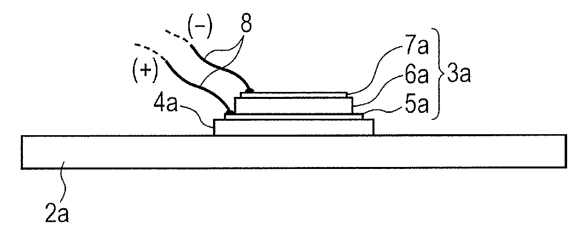
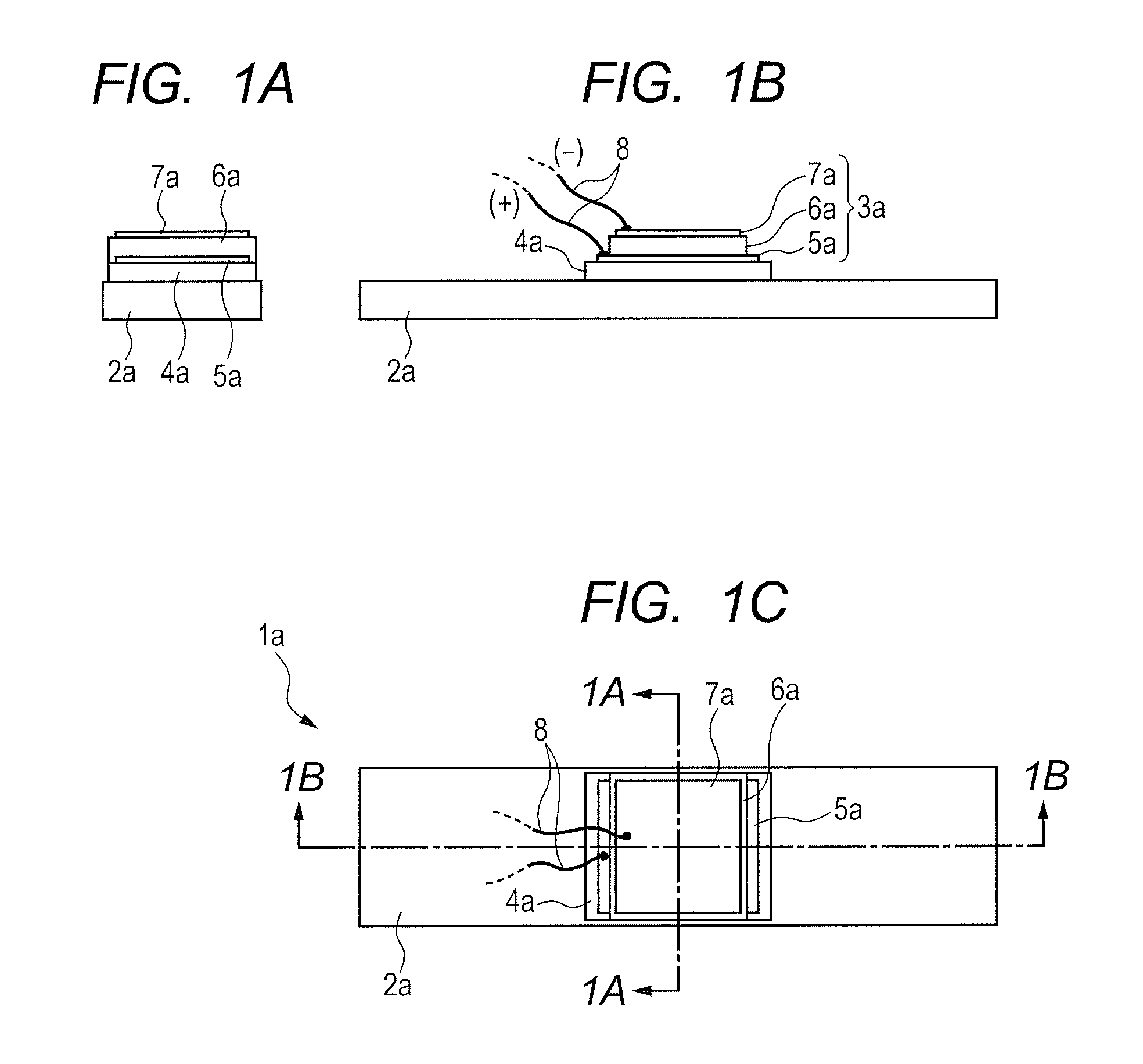
[0042]Now, an exemplar configuration of a vibrating body according to the present invention will be described below as Example 1 by referring to FIGS. 1A through 1C. The vibrating body of this example includes a substrate and a piezoelectric element having a piezoelectric layer and electrode layers and rigidly secured to the substrate so as to vibrate the substrate by the vibration energy of the piezoelectric element and output the vibration energy of the substrate.

[0043]More specifically, the vibrating body of this example is so configured as to give rise to longitudinal vibrations on an assumption that the vibrating body 1a is applied to a vibration type drive device as illustrated in FIGS. 1A through 1C. FIG. 1A is a schematic cross-sectional view of the vibrating body taken along the dotted chain line 1A-1A in FIG. 1C and FIG. 1B is a schematic cross-sectional view of the vibrating body taken along the dotted chain line 1B-1B in FIG. 1C.

[0044]The vibrating body 1a has a plate-sh...

example 2

[0123]Now, an exemplar configuration of a vibrating body according to the present invention that is different from the configuration of Example 1 will be described below as Example 2 by referring to FIGS. 5A through 5C. FIG. 5A is a schematic cross-sectional view of the vibrating body taken along the dotted chain line 5A-5A in FIG. 5C, and FIG. 5B is a schematic cross-sectional view of the vibrating body taken along the dotted chain line 5B-5B in FIG. 5C. FIG. 5C is a schematic plan view of the vibrating body.

[0124]The vibrating body 1b illustrated in FIGS. 5A through 5C is prepared on an assumption that it is to be applied to a vibrating type drive unit for linear drive operations as described earlier as prior art drive unit.

[0125]Note that the method of manufacturing such a vibrating body is basically same as the one described above for Example 1. The substrate, the piezoelectric layer, the electrode layers and the ceramic layer of the vibrating body are also basically same as the...

example 3

[0142]Now, an exemplar configuration of a vibrating body according to the present invention that is different from the configuration of Example 1 and that of the configuration of Example 2 will be described below as Example 3 by referring to FIGS. 6A through 6C. FIG. 6A is a schematic cross-sectional view of the vibrating body taken along the dotted chain line 6A-6A in FIG. 6C, and FIG. 6B is a schematic cross-sectional view of the vibrating body taken along the dotted chain line 6B-6B in FIG. 6C. FIG. 6C is a schematic plan view of the vibrating body.

[0143]The vibrating body 1c of this example is formed by sequentially laying the layers as described below on a plate-shaped substrate 2c as illustrated in FIGS. 6A through 6C.

[0144]Namely, a multilayered type piezoelectric element 3c formed by sequentially laying electrode layers 5c-1 and 5c-2, a piezoelectric layer 6c-1, electrode layers 7c-1 and 7c-2, a piezoelectric layer 6c-2 and electrode layers 7c-3 and 7c-4 is disposed on the p...


PUM


Abstract

A vibrating body comprising a substrate a piezoelectric element comprising a piezoelectric layer and electrode layers and joined to the substrate and a ceramic layer between the substrate and the piezoelectric element, wherein the ceramic layer comprises a first region and a second region which is adjacent to the first region in a direction perpendicular to a thickness direction of the ceramic layer, wherein the first region has a quadrangular prism shape, each side of the first region having a length equal to a thickness of the ceramic layer, wherein the second region has a quadrangular prism shape, each side of the second region having the length equal to the thickness of the ceramic layer, and wherein a difference between a porosity of the first region and a porosity of the second region is not greater than 15%.

Description

BACKGROUND OF THE INVENTION[0001]1. Field of the Invention[0002]The present invention relates to a vibrating body, a method of manufacturing the same and a vibration type drive device. More particularly, the present invention relates to a vibrating body including a piezoelectric element rigidly secured onto a substrate, a method of manufacturing the same and a vibration type drive device formed by using such a vibrating body.[0003]2. Description of the Related Art[0004]Piezoelectric elements have been popularly employed as vibration sources of vibrating bodies (to be also referred to as vibrators) in vibration type drive devices (vibration type actuators).[0005]Piezoelectric elements include single plate piezoelectric elements and multilayered piezoelectric elements formed by laying a large number of piezoelectric layers recently (see Japanese Patent Application Laid-Open No. 2004-304887).[0006]FIG. 8 is a schematic perspective view of a known linear type vibration wave (ultrasonic ...

Claims


Application Information

Patent Timeline
IPC IPC(8): H01L41/053H01L41/27
CPCH01L41/053H01L41/27H02N2/0015H02N2/002H02N2/026H02N2/103H10N30/501H10N30/10516H10N30/206H10N30/053H10N30/074H10N30/079H10N30/88H10N30/05
Inventor MARUYAMA, YUTAKAHARADA, MASAHIROIGARASHI, YOSUKETSUBOTA, YASUHIROONO, JUNZABUROUOGAWA, YASUHIRO
Owner CANON KK
Why Eureka
Try Eureka