Dynamic uplink/downlink configuration for time division duplex

a dynamic uplink/downlink and time division technology, applied in the field of mobile communications, can solve the problems of inefficient resource utilization, detection error, and ue will never know the link direction of non-fixed subframes, and achieve the effects of reducing the power consumption of ue, low implementation complexity, and no increase in blind detection

Active Publication Date: 2013-12-19
AVAGO TECH INT SALES PTE LTD
View PDF4 Cites 80 Cited by
  • Summary
  • Abstract
  • Description
  • Claims
  • Application Information

AI Technical Summary

Benefits of technology

[0034]The invention allows dynamic TDD UL / DL configuration that is able to adapt to an instantaneous traffic situation. Furthermore, since the link direction of each non-fixed subframe is known to the UE before detection of the non-fixed subframe, the UE can stop PDCCH detection in the non-fixed subframes set for UL and thereby reduce power consumption of the UE. Furthermore, indicating the TDD UL / DL configuration in advance simplifies UE's implementation of channel estimation filtering.
[0035]Furthermore, by sending the signaling in a predetermined resource, blind detection is not increased at the UE side. Furthermore, by reusing physical control format indicator channel (PCFICH), physical hybrid ARQ indicator channel (PHICH), or a downlink control information (DCI) encoding scheme, the implementation complexity of the invention is low. Furthermore, by using physical channel (PHY) signaling the processing delay is reduced, and it enables the eNB to adjust the TDD UL / DL configuration efficiently to adapt to the traffic. Compared with higher layer signaling, the processing delay is reduced, and it does not require the eNB to predict the traffic situation. The configuration period and link performance of the invention can be controlled by the eNB. Furthermore, the invention enables the UEs to measure the CQI in the non-fixed subframes which helps the eNB scheduling. Furthermore, the invention can reduce the HARQ timing by explicitly indicating whether the non-fixed subframe is DL or UL in the beginning of a current configuration period or in the previous configuration period. Furthermore, the implementation of the invention is transparent to legacy UEs. Therefore it can be introduced to the network in a backward compatible way.

Problems solved by technology

However, since system information is sent at the interval of at least 640 ms, it cannot provide dynamic TDD configuration to adapt to an instantaneous traffic situation, leading to inefficient resource utilization, especially in cells with a small number of users where the traffic situation changes more frequently.
Otherwise, there will be a detection error at the eNB side.
However, the problem with this is that if there is no scheduling grant for a given UE, the UE will never know the link direction of the non-fixed subframes.
Therefore, it cannot use these subframes for RSM measurement, CQI measurement, or filtering for channel estimation.
Moreover, the UE has to monitor the non-fixed subframes for PDCCH before knowing if it is DL or UL, and this increases the UE's power consumption.
Yet another problem is on the HARQ timing: if there is no scheduling grant for a given non-fixed subframe, the UE will not be aware of the real TDD UL / DL configuration.
Therefore, it cannot use the TDD UL / DL configuration dependent.
A solution could be to restrict the HARQ feedback to a fixed subframe, but this would lead to increased HARQ delay.

Method used


Image

  • Dynamic uplink/downlink configuration for time division duplex
  • Dynamic uplink/downlink configuration for time division duplex
  • Dynamic uplink/downlink configuration for time division duplex

Examples


Embodiment Construction

[0042]Reference will now be made in detail to the embodiments of the present invention, examples of which are illustrated in the accompanying drawings.

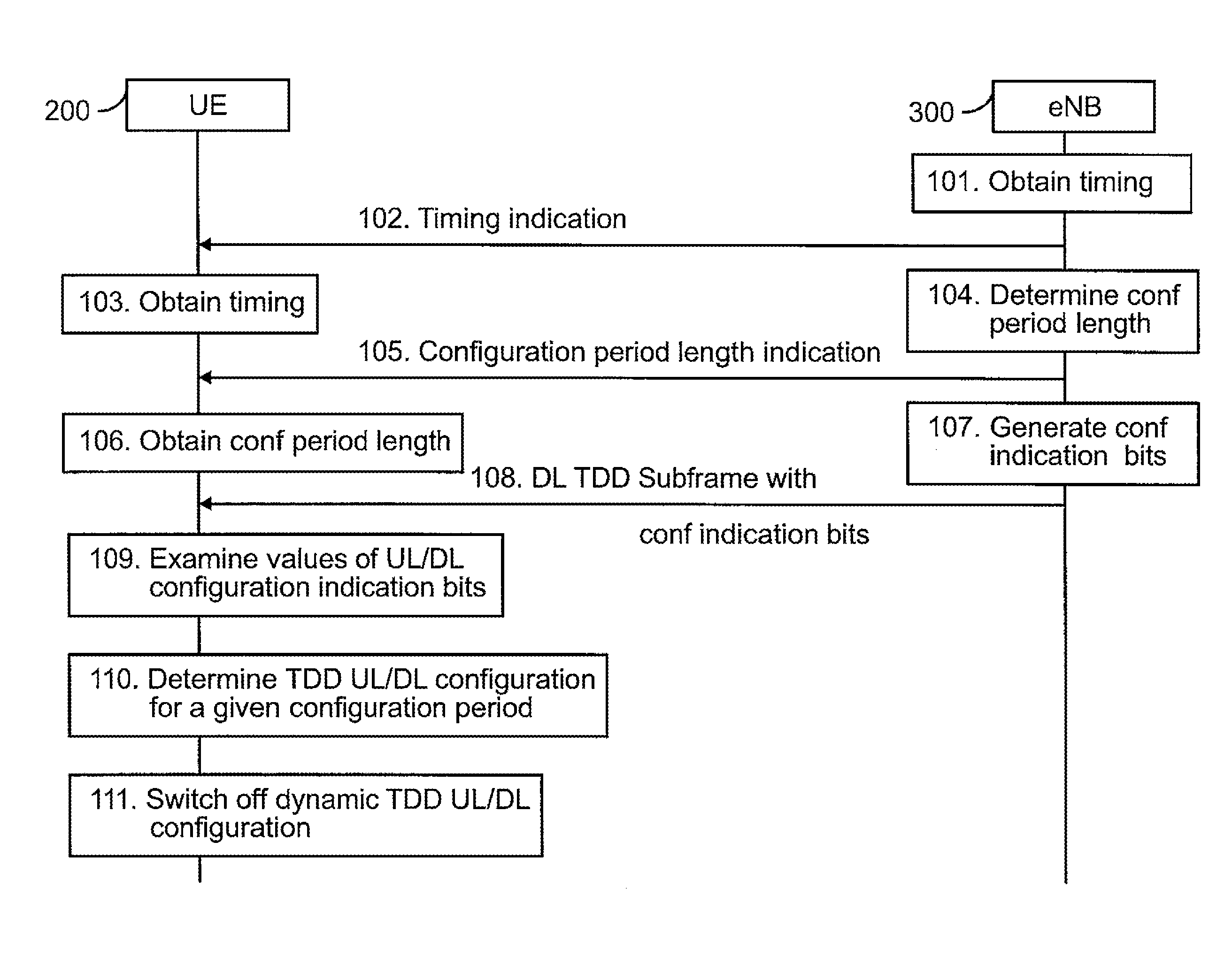
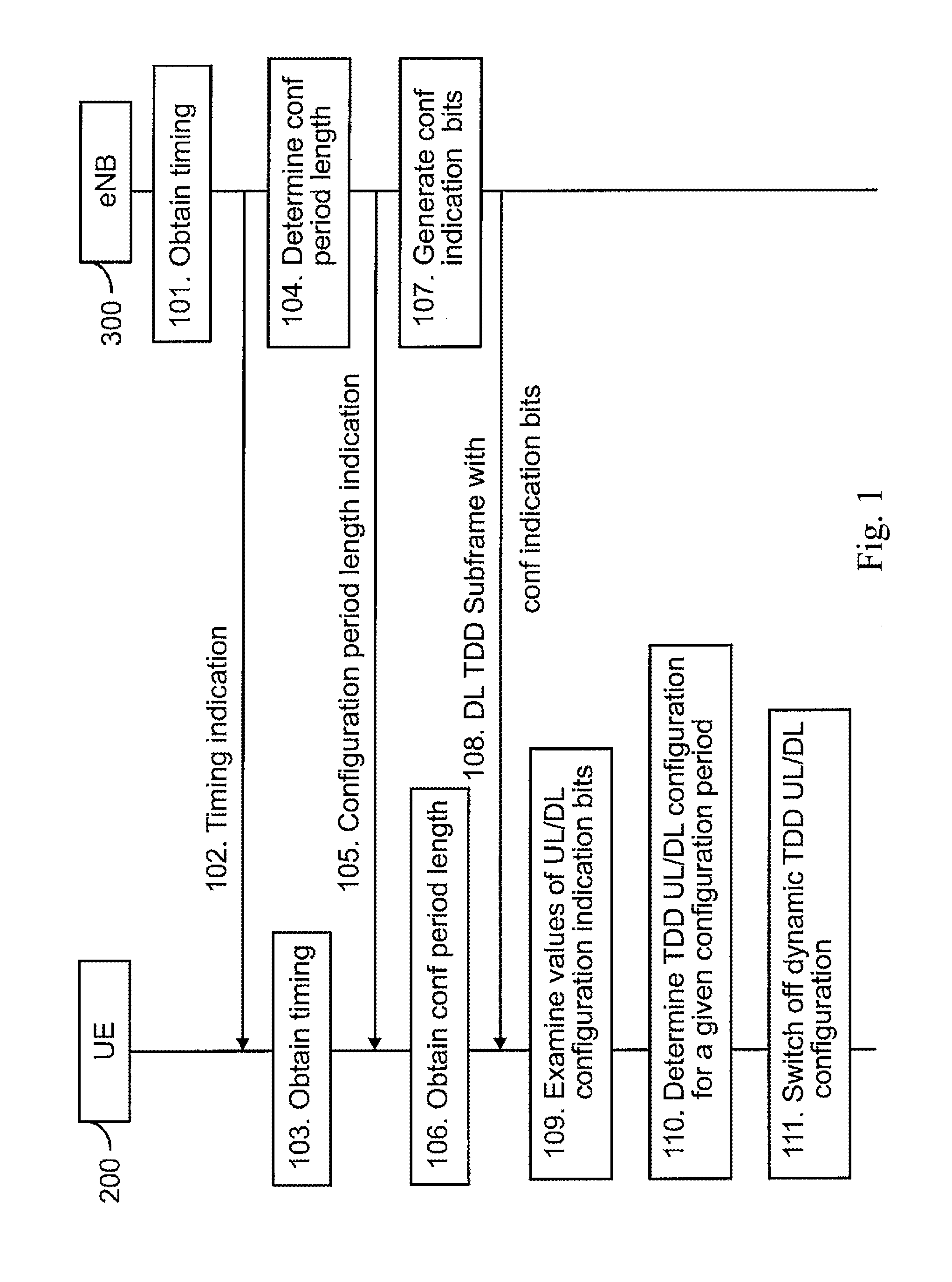
[0043]FIG. 1 is a flow diagram illustrating a method of dynamic uplink / downlink configuration for time division duplex according to an embodiment of the invention.

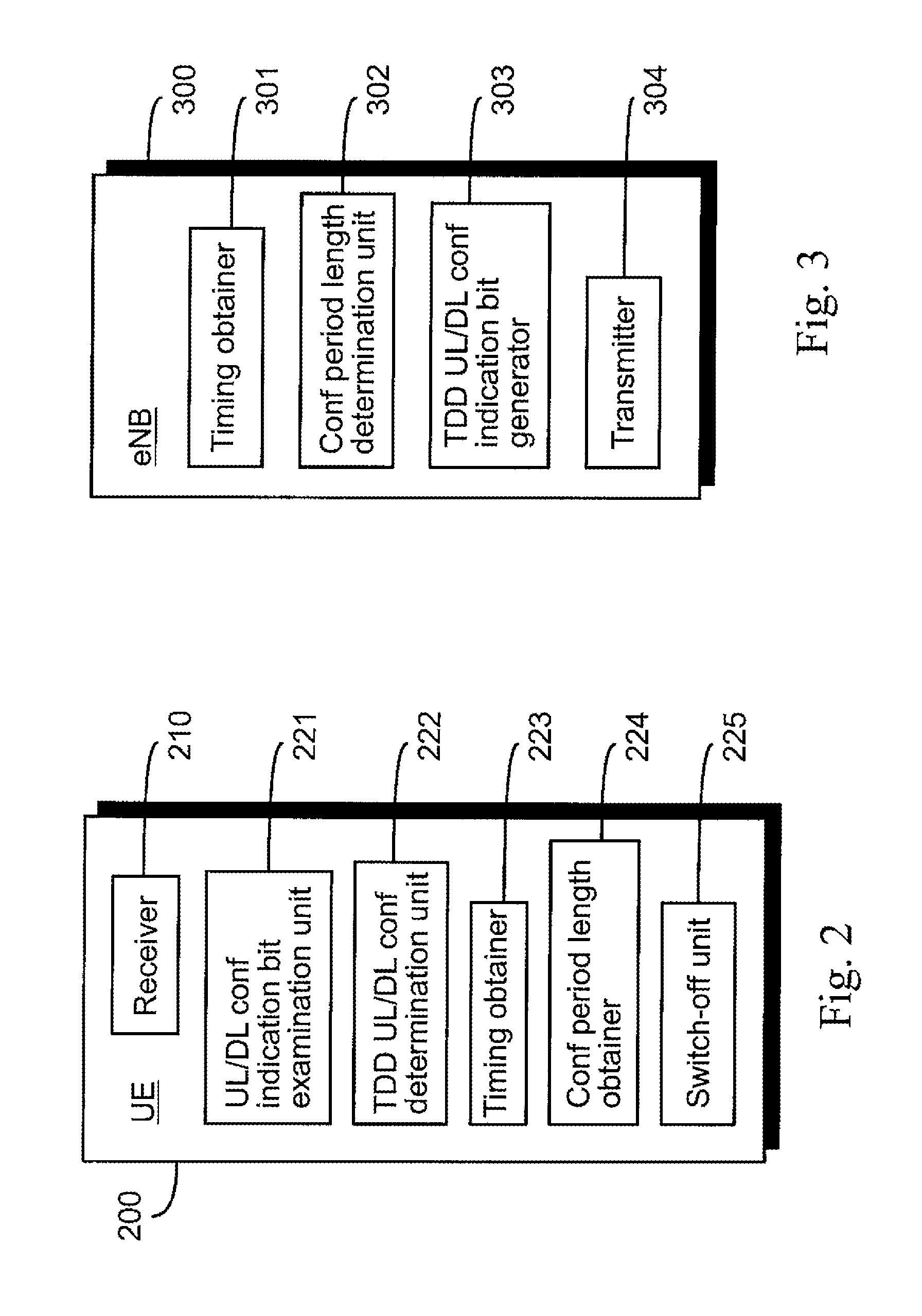
[0044]At step 101, a radio network node 300 obtains timing for at least one time division duplex (TDD) uplink / downlink (UL / DL) configuration indication bit. The radio network node 300 may include e.g. a base station or an evolved Node B (eNB). The radio network node 300 may be deployed e.g. in a mobile communications network utilizing a version of LTE technology, such as LTE Advanced, for example. The radio network node 300 is described in more detail with reference to FIG. 3.

[0045]As discussed in more detail below, the TDD UL / DL configuration indication bit or bits are bits that the present invention uses to indicate which non-fixed subframes of a TDD radio frame (illustrat...


PUM


Abstract

A method and apparatus which allows dynamic TDD UL/DL configuration that is able to adapt to an instantaneous traffic situation. The values of at least one uplink/downlink configuration indication bit in a predetermined region in a received downlink time division duplex subframe of wireless data transmission are examined. A time division duplex uplink/downlink configuration for a predetermined configuration period is determined based on the examined values.

Description

CROSS REFERENCE TO RELATED APPLICATION[0001]This application is a Continuation of PCT International Patent Application No PCT / CN2011 / 071120 filed on Feb. 21, 2011, the entire content of which is incorporated herein by reference.BACKGROUND INFORMATION[0002]The invention relates generally to mobile communications. In particular, the invention relates to methods, computer programs, apparatuses and radio network nodes for dynamic uplink / downlink configuration for time division duplex.[0003]Long Term Evolution (LTE) was introduced in release 8 of 3rd Generation Partnership Project (3GPP) which is a specification for 3rd generation mobile communication systems. LTE is a technique for mobile data transmission that aims to increase data transmission rates and decrease delays, among other things. LTE uses orthogonal frequency division multiple access (OFDMA) as its multiple access method in the downlink. The uplink uses single-carrier frequency division multiple access (SD-FDMA). 3GPP releas...

Claims


Application Information

Patent Timeline
Patent Type & Authority Applications(United States)
IPC IPC(8): H04L5/14
CPCH04L5/1476H04W72/0446H04L1/1671
Inventor GAO, CHUNYANZENG, ERLINHAN, JINGWEI, NAWANG, HAIMING
Owner AVAGO TECH INT SALES PTE LTD
Why Eureka
Try Eureka