Fan Blade Assembly

a technology of fan blades and parts, applied in the field of blade assemblies, can solve the problems of increasing the cost of maintenance and replacement, increasing the cost of conventional fan blade assembly fabrication, etc., and achieves the effects of reducing the whole volume of molds, enhancing the versatility of fan blade assemblies, and reducing the cost of fabrication of fan blade assemblies

Active Publication Date: 2013-12-19
WANG FRANK
View PDF5 Cites 9 Cited by
  • Summary
  • Abstract
  • Description
  • Claims
  • Application Information

AI Technical Summary

Benefits of technology

[0011]According to the primary advantage of the present invention, each of the blades has the same structure so that the manufacturer only needs to make a single blade to fit the base and the cap, thereby reducing the whole volume of the mold, and thereby decreasing the cost of fabrication of the fan blade assembly.
[0012]According to another advantage of the present invention, the base and the cap co-operate to fit the blades of different sizes and specifications, thereby enhancing the versatility of the fan blade assembly. According to a further advantage of the present invention, when one of the blades is worn out or broken during a long-term utilization, the user only needs to remove one of the blades without having to replace all of the blades, thereby decreasing the cost of maintenance and replacement.
[0013]Further benefits and advantages of the present invention will become apparent after a careful reading of the detailed description with appropriate reference to the accompanying drawings.
[0014]FIG. 1 is a front perspective view of a fan blade assembly in accordance with the preferred embodiment of the present invention.
[0015]FIG. 2 is a rear perspective view of the fan blade assembly as shown in FIG. 1.
[0016]FIG. 3 is an exploded perspective view of the fan blade assembly as shown in FIG. 1.

Problems solved by technology

However, the blades are formed integrally on the blade seat so that the manufacturer has to make a mold with a larger volume to fabricate the blade seat with the blades, thereby increasing the cost of fabrication of the conventional fan blade assembly.
In addition, the blades are formed integrally on the blade seat so that when one of the blades is worn out or broken during a long-term utilization, the user has to replace the whole blade seat, thereby increasing the cost of maintenance and replacement.

Method used


Image

  • Fan Blade Assembly
  • Fan Blade Assembly
  • Fan Blade Assembly

Examples


Embodiment Construction

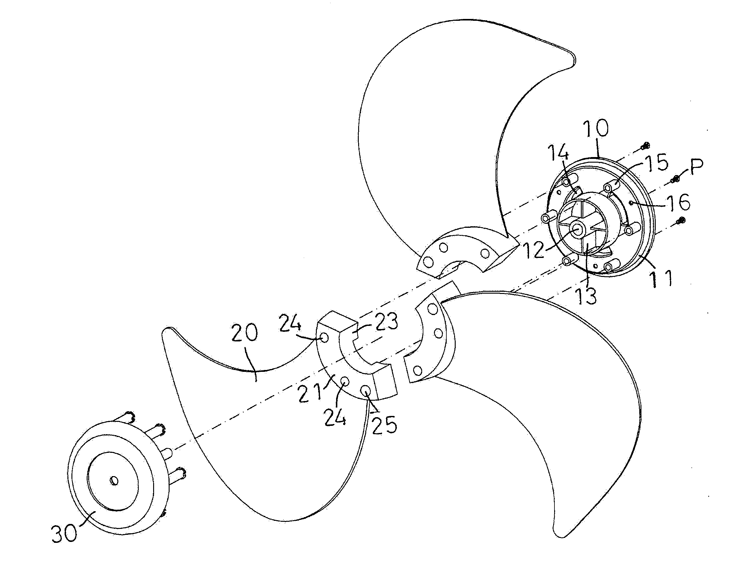
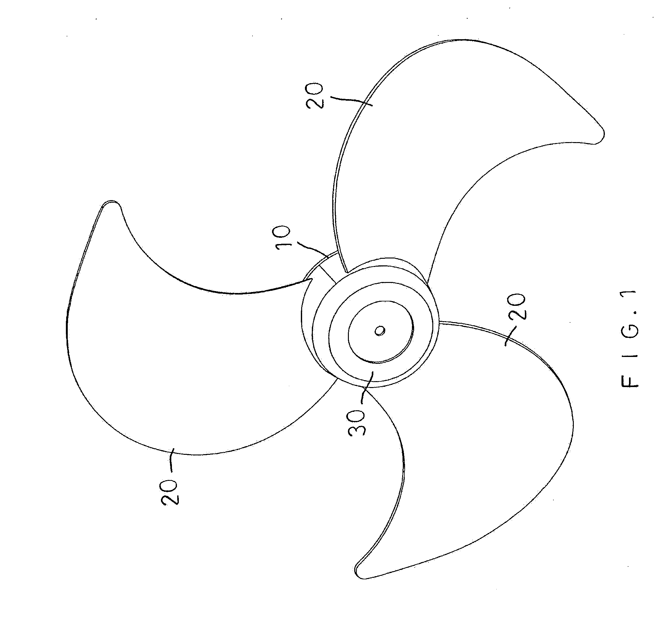
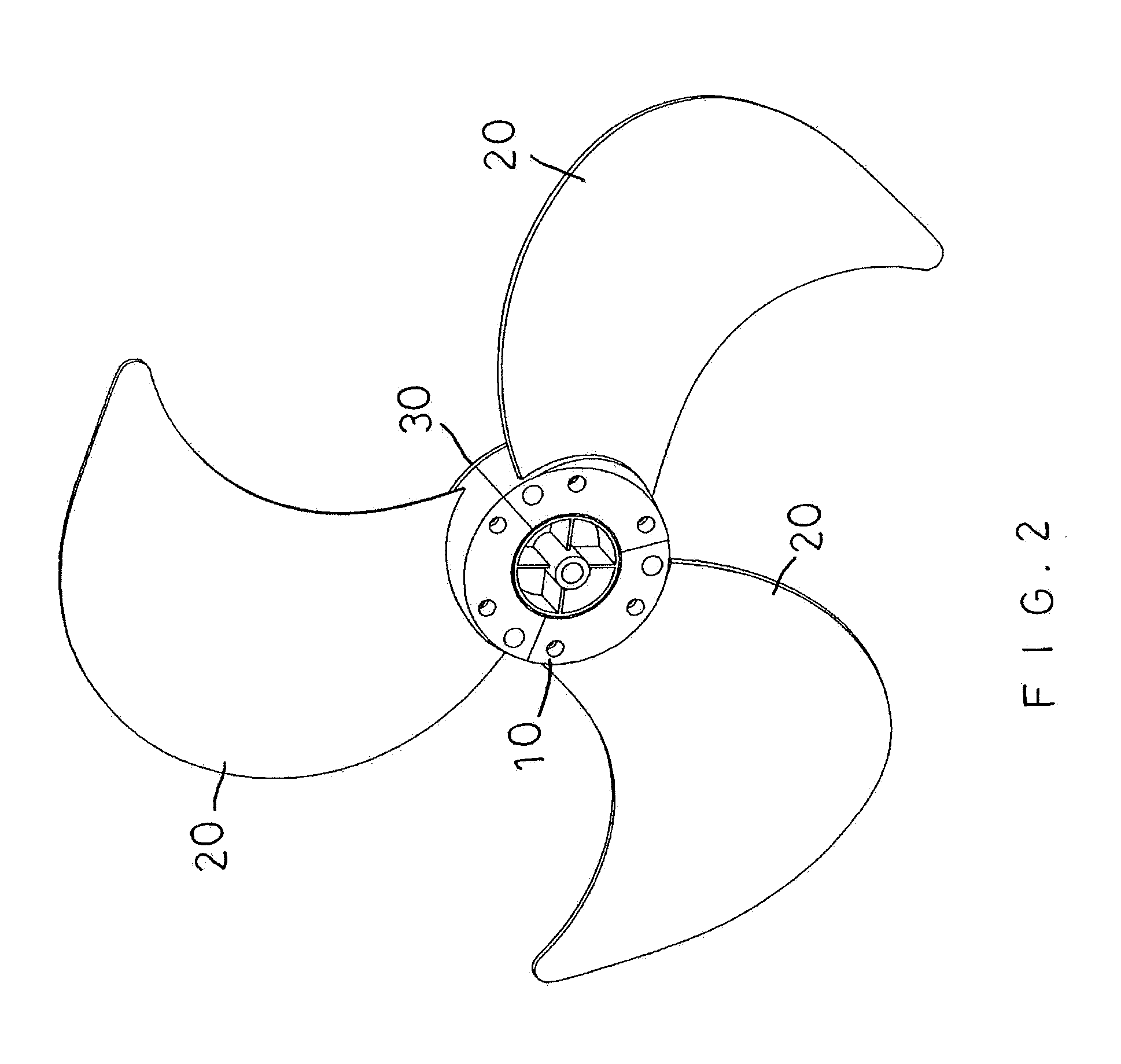
[0025]Referring to the drawings and initially to FIGS. 1-9, a fan blade assembly in accordance with the preferred embodiment of the present invention comprises a base 10, a cap 30 combined with the base 10, and a plurality of blades 20 sandwiched between the base 10 and the cap 30.

[0026]The base 10 has a circular shape and has a periphery provided with a first stepped edge 11. The base 10 has a central portion provided with a hollow shaft 12 to allow passage of a rotor (not shown) of a motor (not shown). The base 10 has a surface provided with a plurality of mounting slots 14 for combining the blades 20, a plurality of positioning tubes 15 for positioning the blades 20, and a plurality of fixing holes 16 for locking the blades 20. The mounting slots 14 of the base 10 are spaced equally from each other. Each of the mounting slots 14 of the base 10 has an arcuate shape. The positioning tubes 15 of the base 10 are spaced equally from each other. The fixing holes 16 of the base 10 are s...


PUM


Abstract

A fan blade assembly includes multiple blades sandwiched between a base and a cap. The base has a hollow shaft and has multiple mounting slots, positioning tubes and fixing holes. Each of the blades has a mounting seat having two lugs. The lugs of any two adjacent blades are inserted into the respective mounting slot. The mounting seat has at least one first through hole to allow insertion of the respective positioning tube, and has at least one second through hole. The cap has a mounting sleeve mounted on the shaft, multiple positioning posts each inserted into the respective first through hole and multiple threaded tubes each inserted into the respective second through hole. The fan blade assembly also includes multiple fastening screws each extended through the respective fixing hole and each screwed into the respective threaded tube.

Description

BACKGROUND OF THE INVENTION[0001]1. Field of the Invention[0002]The present invention relates to a blade assembly and, more particularly, to a fan blade assembly.[0003]2. Description of the Related Art[0004]A conventional fan blade assembly comprises a base, a cap combined with the base, and a blade seat sandwiched between the base and the cap. The blade seat is formed integrally with a plurality of blades which are arranged in a radiating manner. The blade seat usually includes different sizes of about ten, twelve, fourteen and sixteen (10, 12, 14 and 16) inches. However, the blades are formed integrally on the blade seat so that the manufacturer has to make a mold with a larger volume to fabricate the blade seat with the blades, thereby increasing the cost of fabrication of the conventional fan blade assembly. In addition, the blades are formed integrally on the blade seat so that when one of the blades is worn out or broken during a long-term utilization, the user has to replace ...

Claims


Application Information

Patent Timeline
Patent Type & Authority Applications(United States)
IPC IPC(8): F04D29/34
CPCF04D29/34F04D29/329
Inventor WANG, FRANK
Owner WANG FRANK
Why Eureka
Try Eureka