Photoacoustic imaging apparatus and photoacoustic imaging method
a technology of photoacoustic imaging and imaging apparatus, which is applied in the field of photoacoustic imaging apparatus and photoacoustic imaging method, can solve the problems of inability to detect measurement targets and increase the cost of such physical means, so as to prevent light from being irradiated into space and improve the safety of human eyes.
- Summary
- Abstract
- Description
- Claims
- Application Information
AI Technical Summary
Benefits of technology
Problems solved by technology
Method used
Image
Examples
first embodiment
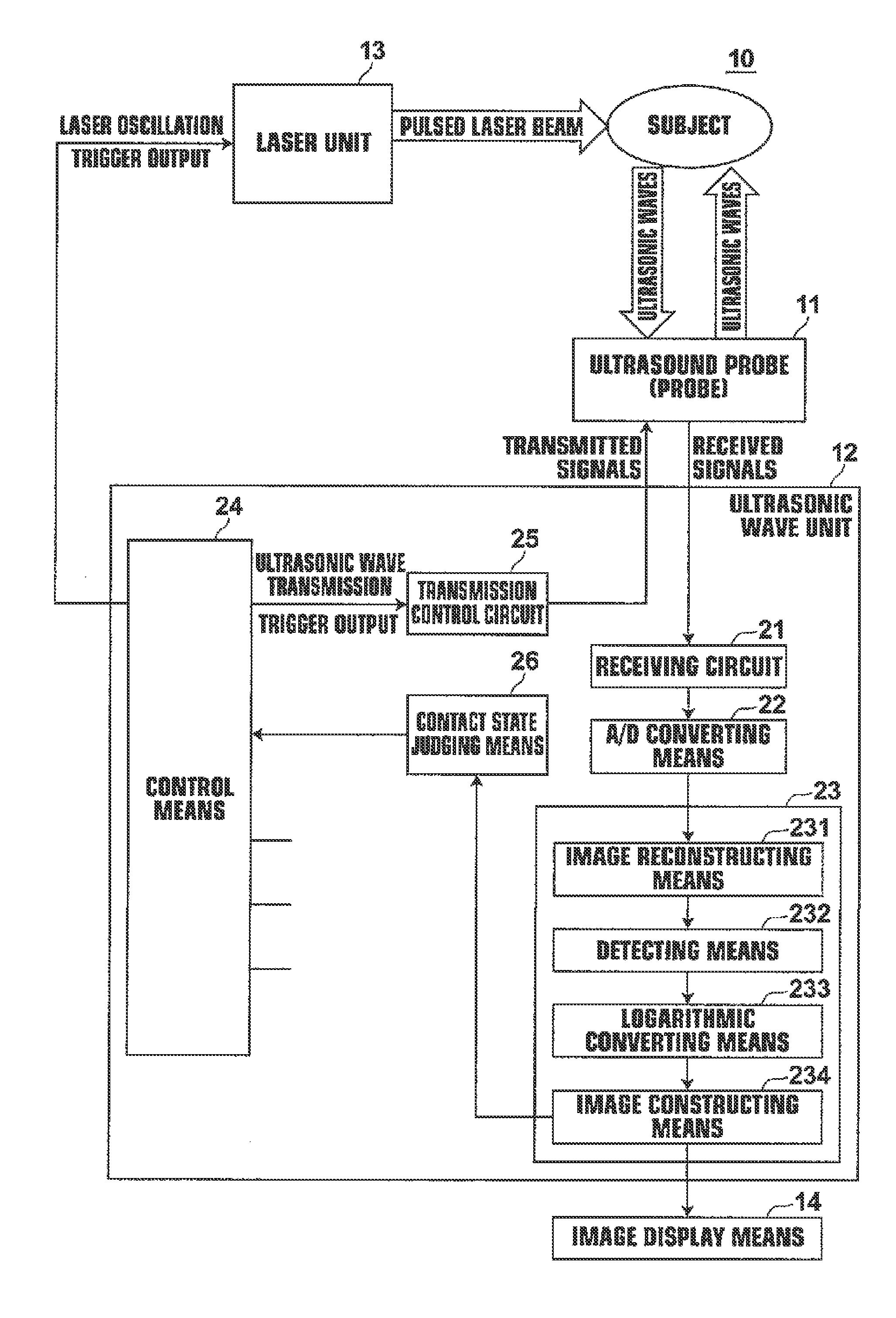
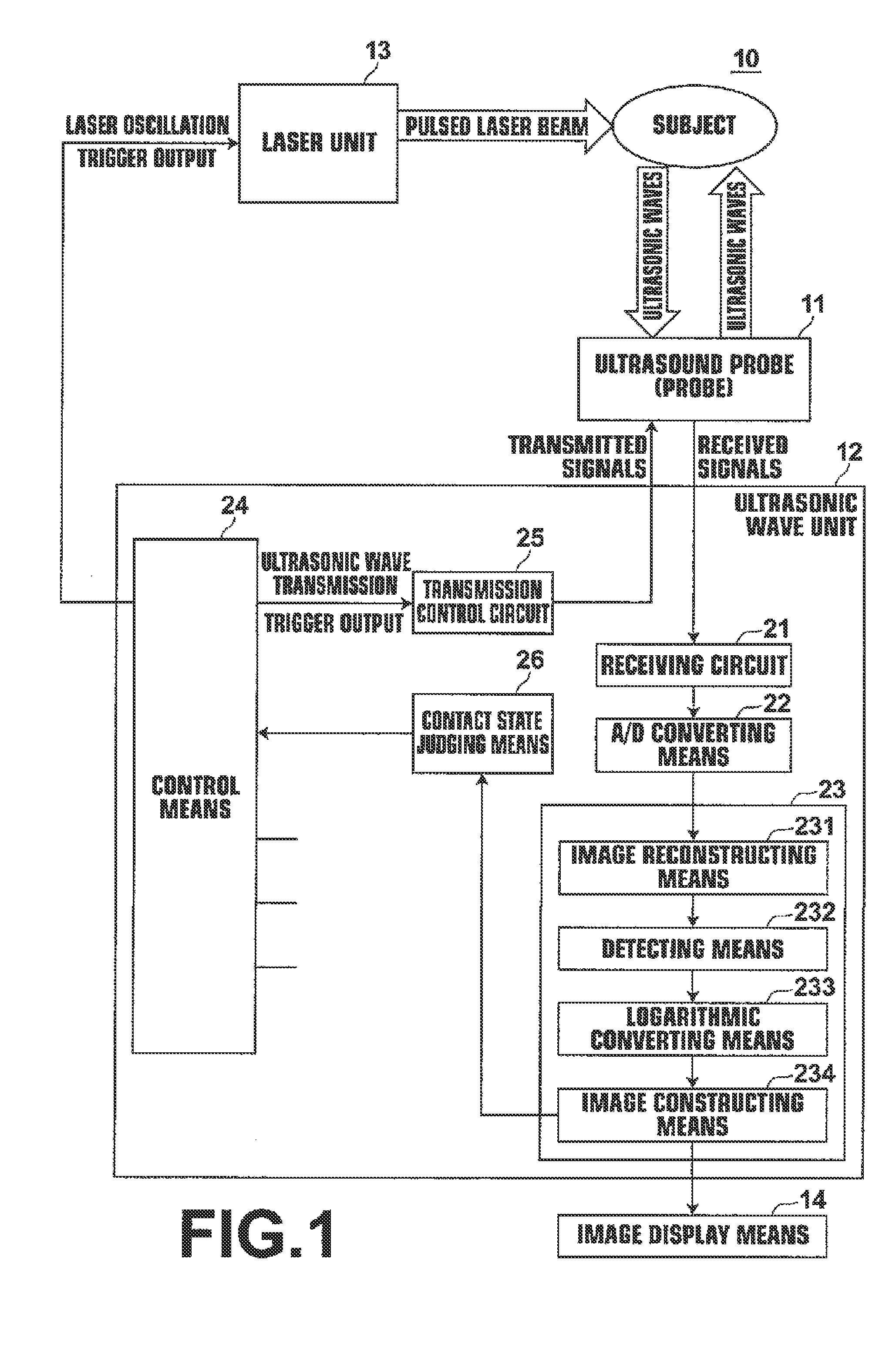
[0062]Hereinafter, embodiments of the present invention will be described in detail with reference to the attached drawings. FIG. 1 illustrates a photoacoustic imaging apparatus 10 according to the present invention. The photoacoustic imaging apparatus 10 (photoacoustic image diagnosis apparatus) includes: an ultrasound probe (probe) 11; an ultrasonic wave unit 12; and a light source (laser unit) 13. The photoacoustic image diagnosis apparatus 10 is capable of generating both ultrasound images and photoacoustic images. The laser unit 13 generates a light beam (laser beam) to be irradiated onto a subject when generating a photoacoustic image. The wavelength of the laser beam may be set as appropriate according to observation targets. The laser beam output by the laser unit 13 is guided to the probe 11 by light guiding means, such as an optical fiber.
[0063]The probe 11 includes a light emitting section that emits the laser beam guided thereto from the laser unit 13 onto subjects. In a...
third embodiment
[0119]The data separating means 236 separates the ultrasound data, the first photoacoustic data, and the second photoacoustic data, which are stored in the reception memory 235. The data separating means 236 provides the reflected ultrasonic wave data to an ultrasound image reconstructing means 240. The data separating means 236 provides the first and second photoacoustic data to the 2 wavelength data complexifying means 244. The reflected ultrasonic wave data output from the data separating means 236 to the ultrasound image reconstructing means 240 is used to generate an ultrasound image and a contact state judging means 26 judges a contact state of the probe 11 based on the generated ultrasound image in the same manner as in the
[0120]The 2 wavelength data complexifying means 244 generates complex number data, in which one of the first photoacoustic data and the second photoacoustic data is designated as a real part, and the other is designated as an imaginary part. Hereinafter, a ...
second embodiment
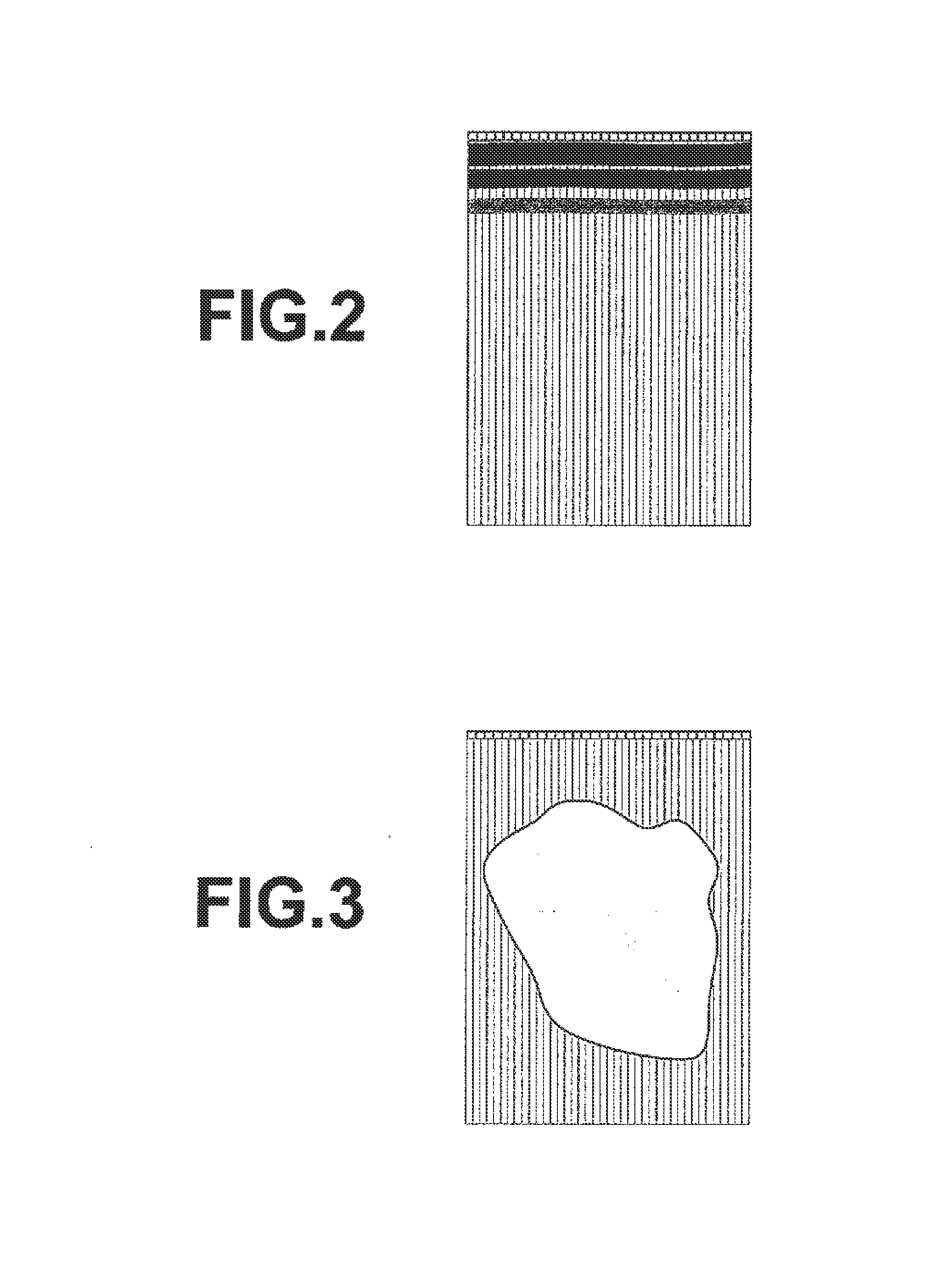
[0143]In greater detail, if there are ultrasonic transducers corresponding to 192 channels, an ultrasound image may be generated for a central portion by transmitting and receiving ultrasonic waves with the central 64 channels, and whether the probe 11 is in contact with a subject may be judged based on the ultrasound image of the central portion. In the second embodiment as well, ultrasonic waves may be transmitted and received not by all of the ultrasonic transducers of the probe 11, but only by ultrasonic transducers corresponding to a portion of an imaging range of a photoacoustic image. In this case, whether the probe 11 is in contact with a subject may be judged based on the ultrasonic wave signal waveform of at least one channel within the range at which ultrasonic waves were transmitted and received, at step B4.
[0144]In addition, in the case that the imaging range of photoacoustic images is divided into blocks, the contact state judging means 26 may judge whether the probe i...
PUM
 Abstract
Description
Claims
Application Information
 - R&D
- Intellectual Property
- Life Sciences
- Materials
- Tech Scout
- Unparalleled Data Quality
- Higher Quality Content
- 60% Fewer Hallucinations
Browse by: Latest US Patents, China's latest patents, Technical Efficacy Thesaurus, Application Domain, Technology Topic, Popular Technical Reports.
© 2025 PatSnap. All rights reserved.Legal|Privacy policy|Modern Slavery Act Transparency Statement|Sitemap|About US| Contact US: help@patsnap.com


