Pneumatic tire and manufacturing method of the same

a pneumatic tire and manufacturing method technology, applied in the field of pneumatic tires, can solve the problems of generating defect affecting the quality of pneumatic tires, etc., and achieves the effects of suppressing defects, improving high-speed durability, and improving forming efficiency of tread rubber

Inactive Publication Date: 2013-12-26
TOYO TIRE & RUBBER CO LTD
View PDF9 Cites 3 Cited by
  • Summary
  • Abstract
  • Description
  • Claims
  • Application Information

AI Technical Summary

Benefits of technology

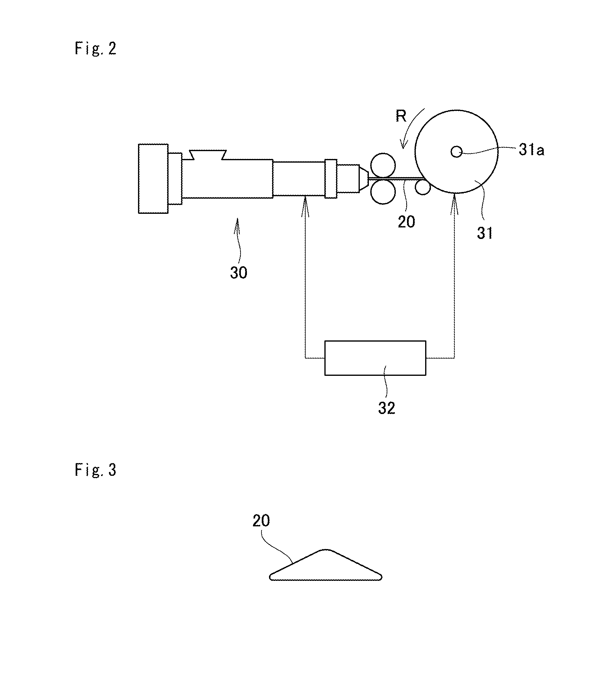
[0020]According to the manufacturing method, since the tread rubber can be formed by one winding process without disconnecting the ribbon rubber from the start point to the terminal end, it is possible to improve a forming efficiency of the tread rubber. Further, as mentioned above, it is possible to improve the high-speed durability, and it is further possible to suppress the defect.
[0021]In order to further improve the high-speed durability, it is preferable to arrange the winding terminal end at the forming position of the main groove extending in the tire peripheral direction.

Problems solved by technology

However, in the pneumatic tire according to JP-A-2006-130880, since the winding start end and the winding terminal end of the ribbon rubber are arranged in the tread center portion, and greater centrifugal force is applied to the center portion of the tread rubber in comparison with the tread end, a failure starting from the winding terminal end tends to be generated in comparison with the case that the winding start point and the winding terminal end exist at the tread ends, and a high-speed durability is deteriorated.
On the other hand, in the pneumatic tire according to JP-A-2002-46194, since the winding start point and the winding terminal end of the ribbon rubber are arranged in the tread ends, and the tread ends are generally formed as a tapered shape, it is hard to appropriately press the ribbon rubber which is wound to a position coming to the tread end by a following roller (stitcher) in a ribbon rubber winding step, and a defect tends to be generated.

Method used


Image

  • Pneumatic tire and manufacturing method of the same
  • Pneumatic tire and manufacturing method of the same
  • Pneumatic tire and manufacturing method of the same

Examples


examples

[0067]A description will be given below of examples which effectively show the structure and the effect of the present invention. In this case, the high-speed durability was evaluated by using a test tire having a tire size 215 / 45R17. The high-speed durability was tested on the basis of a condition about tire of a speed mark H (210 km / h) which was defined as load / speed performance test procedure by a supplementary provision 7 of Regulation No. 30 of Economic Commission for Europe (Regulation No. 30 Uniform Provisions Concerning the Approval of Pneumatic Tires for Motor Vehicles and Their Trailers). The high-speed durability was evaluated by traveling at a high speed by a drum tester until the tire broke down, according to a method of increasing the traveling speed at 10 km / h per ten minutes. Therefore, the higher speed indicates the more excellent high-speed durability.

example 1

[0069]The tread rubber was formed by winding the ribbon rubber via the route shown in FIG. 6. The winding start end S1 and the winding terminal end E1 of the ribbon rubber 20 were arranged respectively at positions which were 12.5% of the maximum width W of the tread rubber from the tread ends P1 and P2 toward the center side. The same structures as the comparative example were applied except the above.

example 2

[0070]The tread rubber was formed by winding the ribbon rubber via the route shown in FIG. 8. The winding start end S2 and the winding terminal end E2 of the ribbon rubber 20 were arranged respectively at positions which were 20% of the maximum width W of the tread rubber from the tread ends P1 and P2 toward the center side. The same structures as the comparative example were applied except the above.


PUM

PropertyMeasurementUnit
angleaaaaaaaaaa
thicknessaaaaaaaaaa
widthaaaaaaaaaa

Abstract

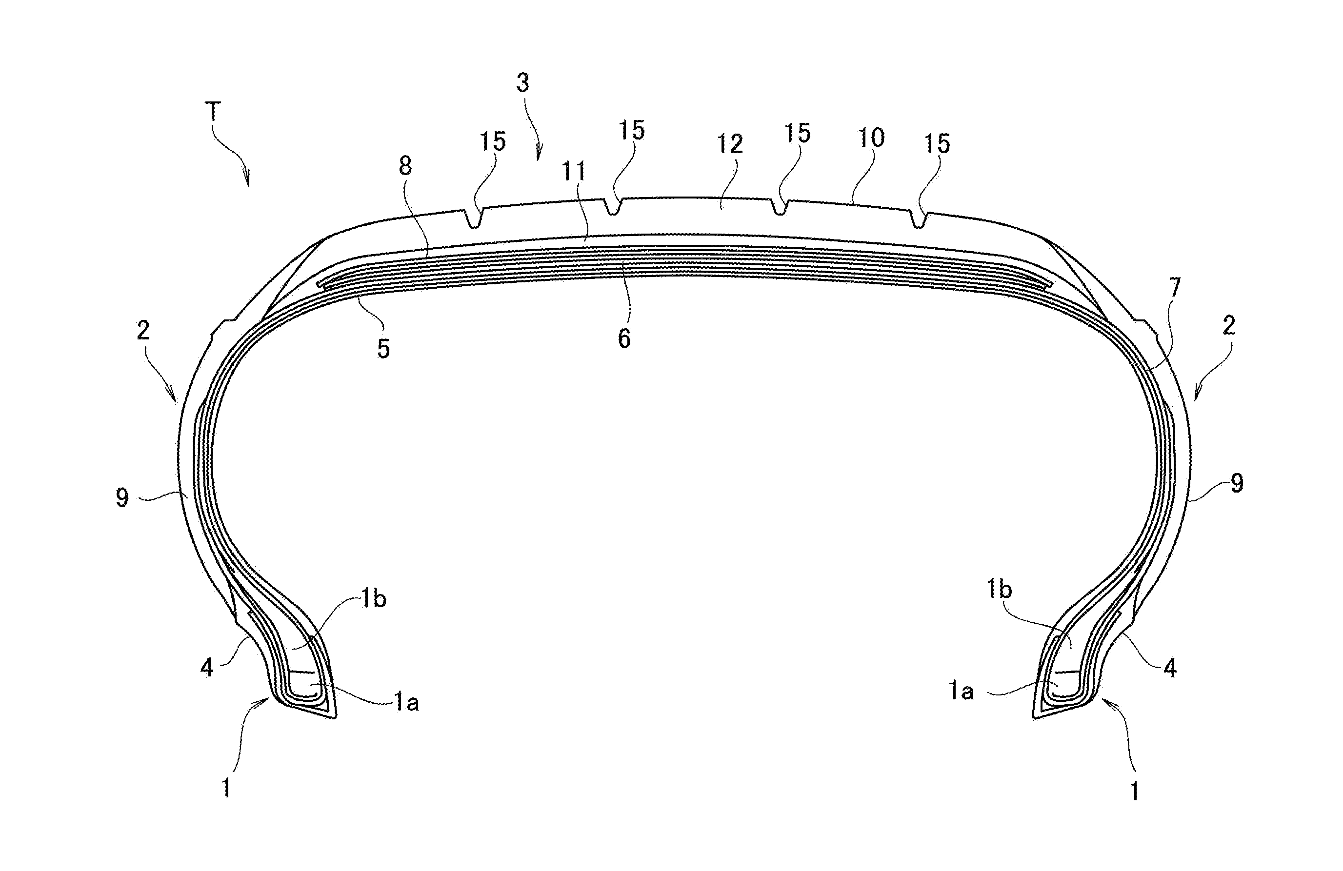
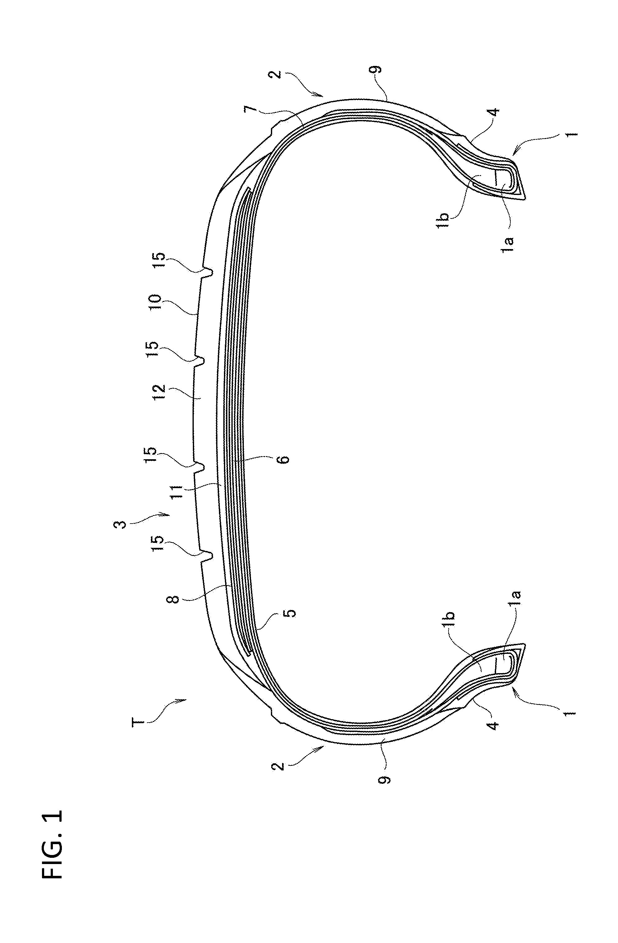
A tread rubber of a pneumatic tire is formed by a ribbon rubber which is spirally wound around a tire rotating axis. The ribbon rubber is wound toward one side in a tire width direction from a start point which is positioned closer to a center side than tread ends in a tire meridian cross section, is next folded back to the other side in the tire width direction at the tread end on the one side, is wound toward the tread end on the other side beyond the start point, is next folded back to the one side in the tire width direction at the tread end on the other side, and is wound toward an end point. The ribbon rubber has the winding start end and the winding terminal end at tread end vicinity portions avoiding the tread ends and a tread center portion.

Description

BACKGROUND OF THE INVENTION[0001]1. Field of the Invention[0002]The present invention relates to a pneumatic tire having a tread rubber, and a manufacturing method of the same.[0003]2. Description of the Related Art[0004]Conventionally, there has been proposed a so-called ribbon winding construction method which forms a tread rubber by spirally winding an unvulcanized ribbon rubber around a tire rotating axis to an outer peripheral surface of an approximately cylindrical rotation support body, while overlapping a side edge thereof.[0005]As one example of a pneumatic tire in which the tread rubber is formed by the ribbon winding construction method, for example, JP-A-2006-130880 discloses a pneumatic tire structured such that a ribbon rubber is wound from a starting point which is positioned in a center portion of a tread toward one side in a tire width direction in a tire meridian cross section, is next folded back to the other side in the tire width direction in a tread end on the ...

Claims


Application Information

Patent Timeline
Patent Type & Authority Applications(United States)
IPC IPC(8): B60C11/00B29D30/08
CPCB60C11/0008B29D30/08B29D30/60Y10T152/10495
Inventor INOUE, YUJI
Owner TOYO TIRE & RUBBER CO LTD
Why Eureka
Try Eureka