Sheet conveying apparatus

Active Publication Date: 2013-12-26
CANON KK
View PDF6 Cites 7 Cited by
  • Summary
  • Abstract
  • Description
  • Claims
  • Application Information

AI Technical Summary

Benefits of technology

[0010]The invention has been made in light of the above problems, and it is desirable to provide a guide member with excellen

Problems solved by technology

However, in the guide member based on the elastic body formed of the thin film member proposed hitherto, the guide member itself may be worn out by an edge of a leading e

Method used


Image

  • Sheet conveying apparatus
  • Sheet conveying apparatus
  • Sheet conveying apparatus

Examples


Example

First Embodiment

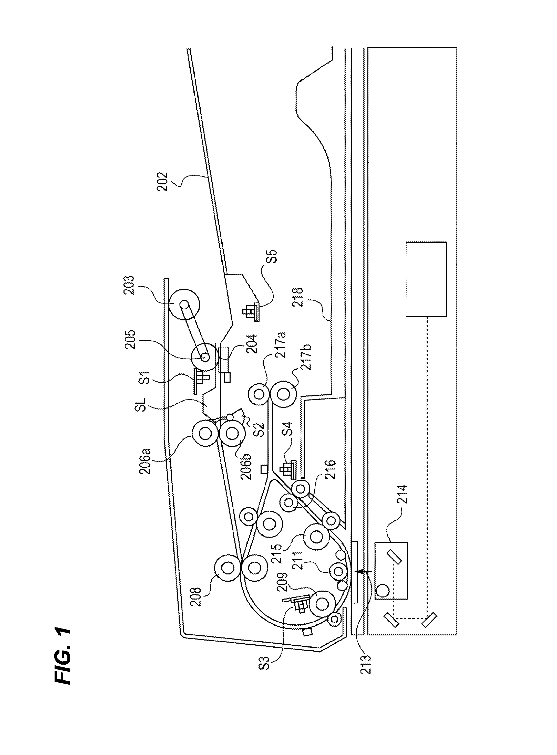
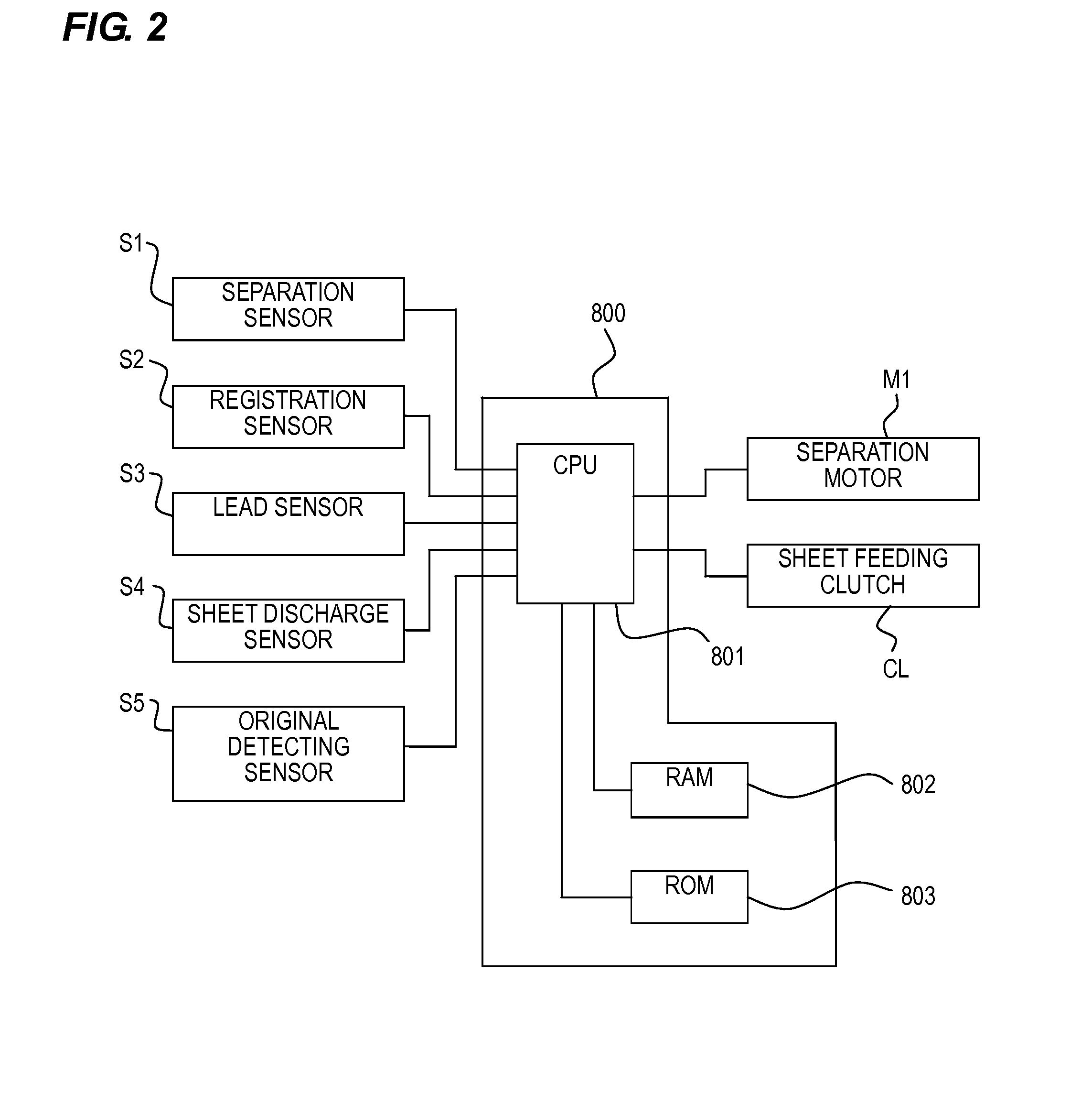
[0026](Overall Configuration of Scanner Apparatus) FIG. 1 is a cross-sectional view illustrating a configuration of a scanner apparatus that reads an image of a sheet according to a first embodiment of the invention. In addition, FIG. 2 is a block diagram illustrating a configuration of a main driving control system of the scanner apparatus illustrated in FIG. 1.

[0027]When a sheet bundle is set on an original tray 202, it is determined that there is an original by an original detecting sensor S5. When a reading operation start is input by a user, a separation motor M1 is driven to drive a pickup roller 203 and a separation roller 205, and the sheet bundle is separated sheet by sheet by a separation pad 204 and is conveyed into the apparatus. In addition, a separation sensor S1 detects that the sheet is positioned at the separation roller 205.

[0028]When a leading end of the sheet reaches a registration sensor S2, the leading end of the sheet is conveyed by the separat...

Example

Second Embodiment

[0087]Next, a scanner apparatus according to a second embodiment of the invention will be described.

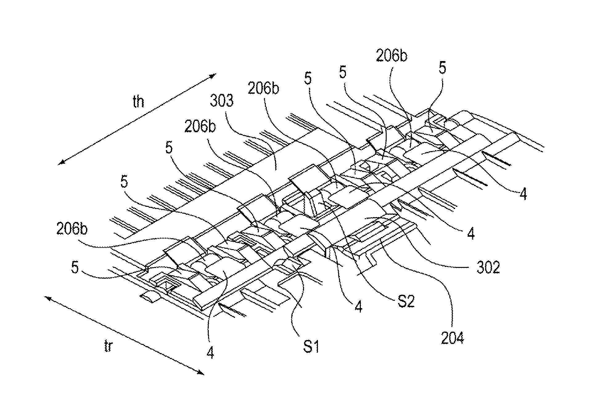
[0088](Configuration of Registration Correction Mechanism) FIG. 9 is a perspective view illustrating a configuration of a registration correction mechanism of a scanner apparatus and peripheral portions thereof according to the embodiment. In the figure, the same reference numerals and signs are given to the same or similar portions as the configurations of the first embodiment, and the repeated description is not provided. In addition, the portions other than the configuration illustrated in FIG. 9 are the same as those of the first embodiment, and the repeated description is not provided.

[0089]In the figure, a separation pad 204 and a registration roller 206b are sequentially disposed in the conveying direction tr. In addition, in the thrust direction th that is the direction perpendicular to the conveying direction on the conveying direction face, a plurality of re...


PUM


Abstract

A sheet conveying apparatus includes: a first conveying guide that has a first conveying face of a conveying path; a second conveying guide that has a second conveying face opposed to the first conveying face; and a guide portion that is provided at any one of the first conveying guide and the second conveying guide, the guide portion has an elastic member that is fixed to one of the first conveying guide and the second conveying guide, and a rigid member that is provided on the face side of the elastic member on which the sheet passes and that has a surface more rigid than that of the elastic member, and the elastic member is deformed by pressing of the conveyed sheet when the sheet passes through the guide portion.

Description

BACKGROUND OF THE INVENTION[0001]1. Field of the Invention[0002]The present invention relates to a sheet conveying apparatus used in an image forming apparatus such as a copying machine and a printer and in an image reading apparatus such as a scanner.[0003]2. Description of the Related Art[0004]An image reading apparatus such as a scanner includes an image reading portion that reads an image of a sheet, and a sheet conveying apparatus that conveys the sheet from a sheet tray to the image reading portion. In addition, an image forming apparatus such as a printer includes an image forming portion that forms an image on a sheet, and a sheet conveying apparatus that supplies the sheet from a sheet tray to the image forming portion.[0005]Such a sheet conveying apparatus is provided with a guide member that applies a force to the sheet to be conveyed by an elastic body.[0006]For example, Japanese Patent Laid-Open No. 7-76438 discloses a biasing member which applies a force to a sheet to ...

Claims


Application Information

Patent Timeline
IPC IPC(8): B65H9/00B65H9/08
CPCB65H9/002B65H9/08B65H3/0669B65H3/0684B65H3/5223B65H5/062B65H5/36B65H7/02B65H9/006B65H2403/72B65H2404/531B65H2404/552B65H2404/61B65H2511/51B65H2513/512B65H2553/82B65H2601/522B65H2701/1311B65H2701/1313B65H2801/39B65H2220/01B65H2220/02B65H2220/11B65H2220/03
Inventor MITAMURA, AKIYUKI
Owner CANON KK
Why Eureka
Try Eureka