

Rotary tool
- Summary
- Abstract
- Description
- Claims
- Application Information
AI Technical Summary
Benefits of technology
Problems solved by technology
Method used
Image

Examples
examples
[0055]While the present invention will be described in more detail hereinafter with reference to examples, the present invention is not limited thereto.
example 9
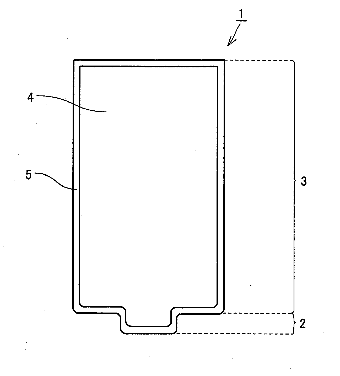
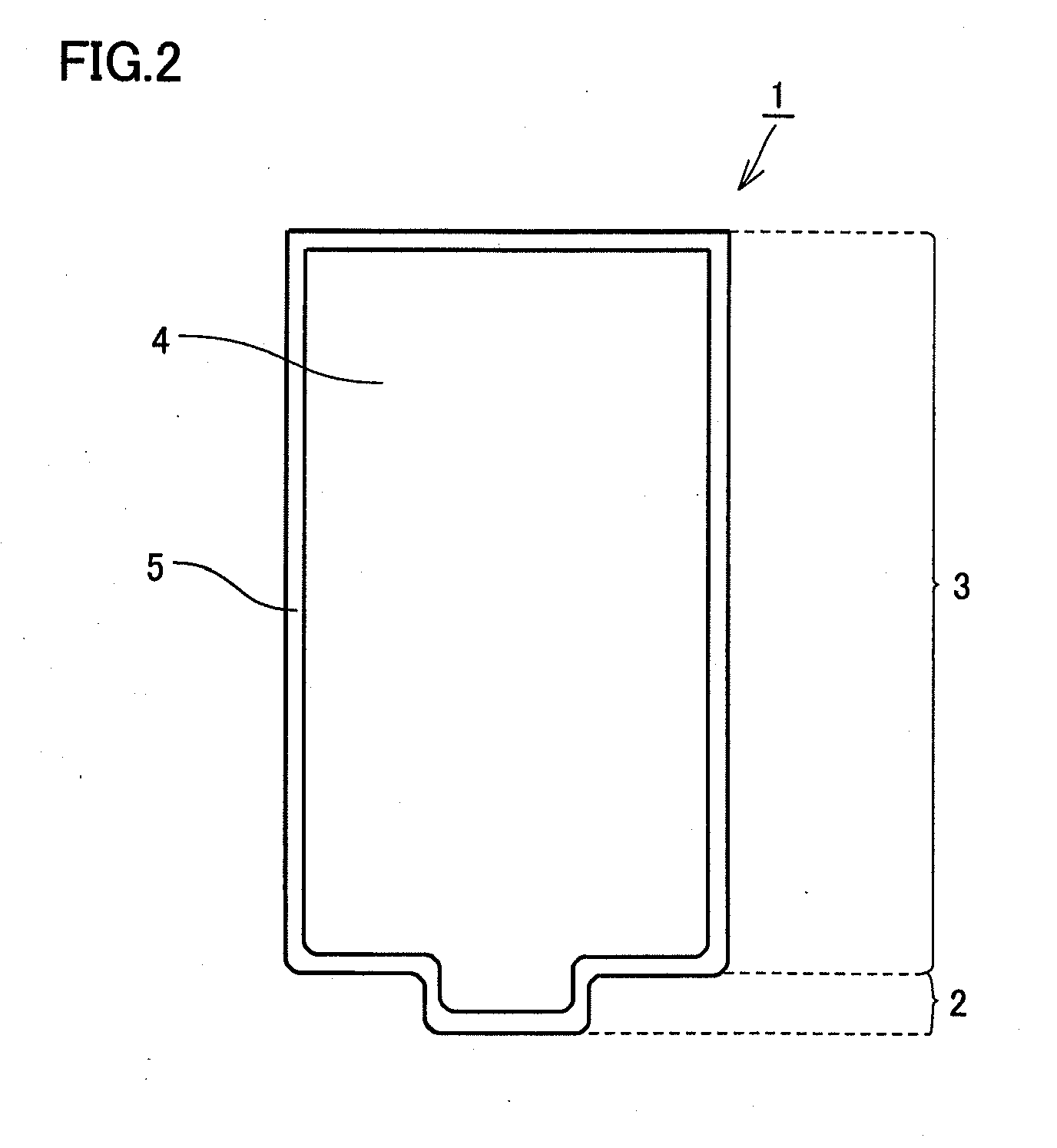
[0066]The base material of the friction stir welding tool of Example 2 was coated with a coating layer having a thickness of 10 μm by means of the cathode arc ion plating method. The coating layer was made of Al0.6Ti0.35Si0.05N. In this way, a friction stir welding tool of Example 9 was fabricated to have the shape shown in FIG. 2. The coating layer made of Al0.6Ti0.35Si0.05N had an oxidation starting temperature of 1130° C. The oxidation starting temperature was found by using a TG / DTA device (Trademark: TG-DTA2020SA (provided by Bruker)) to measure a temperature at which the weight of the coating layer was increased.
example 10
[0067]A friction stir welding tool of Example 10 was fabricated by means of a method similar to that in Example 9 except that the coating layer of Example 9 was changed to have a composition of Ti0.5Al0.5N. The coating layer thus made of Ti0.5Al0.5N had an oxidation starting temperature of 970° C.
[0068]Although the coating layer was formed by means of the cathode arc ion plating method in each of Examples 9 and 10, the coating layer can also be formed by means of, for example, a balanced or unbalanced sputtering method. It should be noted that in each of the examples, the thickness of the coating layer was measured by directly observing the cross sectional surface thereof using an SEM or a TEM.
[0069]
[0070]Each of the friction stir welding tools fabricated in the examples and the comparative examples as above performed spot friction stir welding (FSW) at 3000 spots under conditions shown in Table 2 below. It should be noted that Comparative Example 3 had a defect before joining at 10...
PUM
| Property | Measurement | Unit |
|---|---|---|
| Temperature | aaaaa | aaaaa |
| Length | aaaaa | aaaaa |
| Thickness | aaaaa | aaaaa |
Abstract
Description
Claims
Application Information