Centrifugally cast composite roller and method for manufacturing same

A technology of centrifugal casting and composite rolls, which is applied in the manufacture of tools, chemical instruments and methods, rolls, etc., can solve the problems of increased manufacturing costs, deterioration of processability, foreign matter intrusion, etc., and achieves easy machining, excellent wear resistance, Effect of manufacturing cost reduction

Active Publication Date: 2014-12-17
PROTERIAL LTD
View PDF9 Cites 7 Cited by
  • Summary
  • Abstract
  • Description
  • Claims
  • Application Information

AI Technical Summary

Problems solved by technology

However, the wear resistance of this coupling part is not yet sufficient
Furthermore, in order to cast the coupling part at the end of the shaft part, there is a problem that casting defects such as foreign matters are likely to occur at the joint boundary between the two.
In addition, because of the need to flatten the cast part, or to install a mold around the cast part, or to melt and cast the spherical graphite cast iron for the coupling part different from the inner layer, there is also a problem of increased manufacturing cost. question
[0006] In addition, if the driving-side shaft portion 22 and the driven-side shaft portion 23 are formed of the same hard material, the driven-side shaft portion 23, which does not need to have the same hardness as the driving-side shaft portion 22, becomes too hard and may deteriorate the workability. question

Method used


Image

  • Centrifugally cast composite roller and method for manufacturing same
  • Centrifugally cast composite roller and method for manufacturing same
  • Centrifugally cast composite roller and method for manufacturing same

Examples


Embodiment 1~3 and comparative example 1 and 2

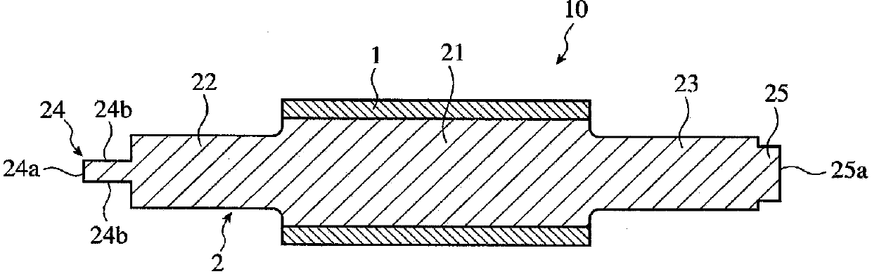
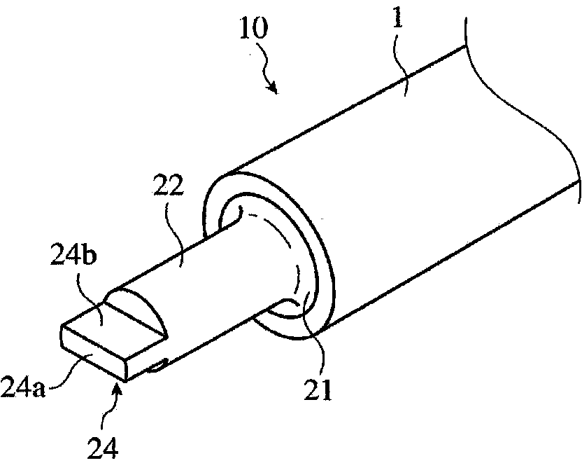
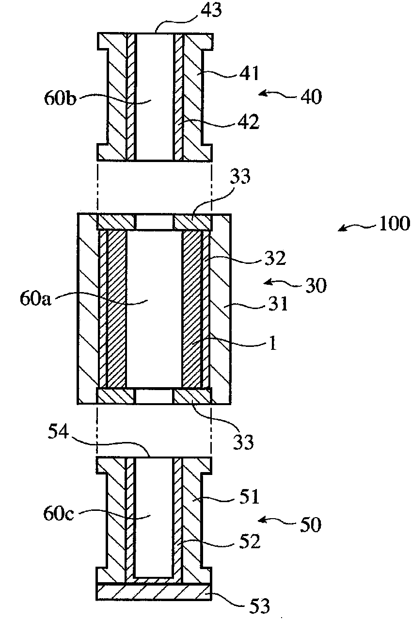
[0121] A cylindrical mold 30 (800 mm in inner diameter, 2500 mm in length) having the structure shown in FIG. After the outer layer 1 is solidified, the cylindrical mold 30 with the outer layer 1 (thickness: 90 mm) formed on the inner surface is erected, and placed on the hollow lower mold 50 (inner diameter: 600 mm, length: 1500 mm) for forming the drive side shaft portion 22 A cylindrical casting mold 30 is vertically arranged, and a hollow upper mold 40 (inner diameter 600mm, length 2000mm) for forming the driven side shaft portion 23 is vertically arranged on the cylindrical casting mold 30, thereby constituting the static mold shown in Fig. 3 (b). Place casting mold 100 for casting.

[0122] A nodular cast iron melt having the composition shown in Table 1 was poured from the upper opening 43 into the cavity 60 of the static casting mold 100 . The liquid level of the nodular cast iron melt is determined by the lower mold 50 for forming the driving side shaft portion 22, the...

Embodiment 4

[0125] After forming an intermediate layer (thickness: 20 mm) of the composition shown in Table 1 on the inner surface of the outer layer 1, the cylindrical mold 30 was erected, and a composite roll was formed in the same manner as in Example 1. As a result of ultrasonic inspection, it was confirmed that the outer layer 1, the middle layer, and the inner layer 2 were firmly welded together.

[0126] For Examples 1 to 4 and Comparative Examples 1 and 2, the casting temperatures of the outer layer, inner layer, and intermediate layer, and the lower mold 50 for forming the drive side shaft portion 22, the cylindrical mold 30 for forming the core portion 21, and the Table 2 shows the average rising speed of the inner layer melt surface in the upper die 40 for forming the movable side shaft portion 23 . The average rate of rise of the molten surface of the inner layer was calculated by measuring the weight of the molten inner layer and measuring the casting time. In addition, the ...


PUM

PropertyMeasurementUnit
Vickers hardnessaaaaaaaaaa

Abstract

A centrifugally cast composite roller in which an outer layer formed by centrifugal casting and an inner layer made from ductile cast iron are integrally welded, wherein: the outer layer has a chemical composition containing at least 0.8 to 3.0% of Cr, 1.5 to 6.0% of Mo, and 1.8 to 5.5% of V, by mass, and comprises an Fe-based alloy in which the graphite area ratio in the metal structure is 0.3 to 10%; the inner layer has a body core part welded to the outer layer, and shaft parts extending integrally from both ends of the body core part, the total amount of Cr, Mo, and V at end sections of both shaft parts being 0.15 to 2.0 mass%, and the difference in the total amount of Cr, Mo, and V between one shaft part and the other shaft part being equal to or greater than 0.2 mass%.

Description

technical field [0001] The present invention relates to a centrifugal casting composite roll having a composite structure in which an outer layer formed by a centrifugal casting method and a tough inner layer are welded and integrated, and a manufacturing method thereof. Background technique [0002] Such as figure 1 with figure 2 As shown, the composite roll 10 for hot rolling is composed of an outer layer 1 in contact with a rolled material, and an inner layer 2 welded to the inner surface of the outer layer 1 and having a different material from the outer layer 1 . The inner layer 2 is composed of a core portion 21 welded to the outer layer 1 , and a driving side shaft portion 22 and a driven side shaft portion 23 integrally extending from the core portion 21 to both sides. At an end portion of the driving side shaft portion 22, a coupling portion 24 for driving torque transmission is integrally provided. In addition, at the end of the driven side shaft portion 23, a ...

Claims


Application Information

Patent Timeline
Patent Type & Authority Applications(China)
IPC IPC(8): B22D13/02B21B27/00C22C37/00C22C37/06
CPCB22D13/02C22C37/06B21B27/032B32B15/011C22C37/08C22C37/10B22D13/023B22D19/16Y10T428/12958B22D13/026B21B27/00C22C37/00
Inventor 小田望濑川尧之野崎泰则服部敏幸
Owner PROTERIAL LTD
Why Eureka
Try Eureka