Portable dual-energy radiographic x-ray perihpheral bone density and imaging systems and methods

a radiographic x-ray and perihpheral bone technology, applied in the field of radiographic bone density measurement and imaging for radiography, can solve the problems of limited availability in large hospitals, high cost of current standard tests performed by whole-body dxa scanner systems, and large number of dxa systems. achieve the effect of reducing energy consumption, limiting low energy transmission, and high energy componen

Inactive Publication Date: 2013-12-26
MA GEORGE W
View PDF1 Cites 26 Cited by
  • Summary
  • Abstract
  • Description
  • Claims
  • Application Information

AI Technical Summary

Benefits of technology

[0008]In one embodiment, a portable, dual-energy radiographic x-ray imaging and bone density measuring system includes an X-ray tube, an X-ray imaging detector, a housing, and an embedded system. The X-ray tube is configured to emit an X-ray beam through a filter positioning mechanism. The filter positioning mechanism includes a high energy filter, a low energy filter, and a shutter configured to block transmission of the X-ray beam. The housing positions the X-ray tube at a distance from the X-ray beam detector, wherein the housing is configured for positioning a forearm between the X-ray tube and the X-ray beam detector. The embedded system is configured to activate the X-ray tube and to control the position of the filter positioning mechanism and imaging data acquisition. In one embodiment, the embedded system is an operating system. In one embodiment, the embedded system manages power requirements, processes data, controls LCD / touchscreen and all system communications that includes USB and wireless communications.
[0009]In one embodiment, the X-ray tube is active for at most two seconds per exposure. In one embodiment, the high energy filter provides a high energy component for transmission through the filter positioning mechanism, and limits low energy transmission. In one embodiment, the high energy filter absorbs lower energy. In one embodiment, the high energy filter provides a high energy component of 40-50 kV or more for transmission through the filter positioning mechanism. In one embodiment, the high energy filter comprises copper and at least one of the group consisting of tin and rhodium. In one embodiment, the low energy filter provides for lower energy transmission of energy through the filter positioning mechanism. In one embodiment, the low energy filter provides for lower energy transmission of energy below 40-50 kV through the filter positioning mechanism. In one embodiment, the low energy filter comprises aluminum and at least one type of material having a K-edge absorption of 40 kV or more. In one embodiment, a material having a K-edge absorption of 40 kV or more is selected from the group consisting of cerium, samarium, gadolinium, and barium.
[0010]In one embodiment, the filter positioning mechanism is actuated by a stepper motor in electric communication with the embedded system. In one embodiment, the filter positioning mechanism is a filter exchanger configured to be rotatably or linearly actuated by a stepper motor. In one embodiment, the stepper motor is a high torque and high speed design that enables to switch one position to another in 100 ms or less. In one embodiment, the embedded system provides high-speed / high bandwidth data transmission configured for transmission of imaging data in less than 100 ms. In one embodiment, the X-ray imaging detector transmits image data through any one of the group consisting of a Gig-Ethernet and a camera link. In one embodiment, the embedded chip system operates the X-ray tube at a duty cycle of approximately 1 / 60, for a one second active pulsed radiation to sixty second inactive period. In one embodiment, the embedded chip system operates the X-ray tube at a duty cycle for a two second active pulsed radiation to one hundred twenty second inactive period. In one embodiment, the embedded can include an operating system configured to process data, control a LCD / touchscreen, manage a power supply, and / or control a communication with any of a wired communication, a USB communication and / or a wireless communication. In one embodiment, the system is configured as a battery powered device.
[0011]In one embodiment, a method for measuring peripheral bone density includes positioning a forearm of a patient between an X-ray source and a beam detector in an X-ray system. The X-ray tube is configured to emit an X-ray beam through a filter positioning mechanism. The filter positioning mechanism includes a high energy filter, a low energy filter, and a shutter configured to block transmission of the X-ray beam. The method includes activating an embedded chip in the X-ray system, with the embedded chip configured to activate the X-ray tube and to control the position of the filter positioning mechanism. In one embodiment, the activating the embedded chip includes activating the X-ray tube for two seconds or less, moving the filter positioning mechanism from a shuttered position to a low energy position with said high energy filter, acquiring low energy data, moving the filter positioning mechanism from the low energy position to a high energy position with said low energy filter, and acquiring high energy data.
[0012]In one embodiment, a method for measuring peripheral bone density includes positioning a forearm of a patient between an X-ray source and a beam detector in an X-ray system. The X-ray tube is configured to emit an X-ray beam through a filter positioning mechanism, the filter positioning mechanism comprising a first energy filter, a second energy filter, and a shutter configured to block transmission of the X-ray beam. In one embodiment, a step includes activating an embedded chip in said X-ray system, the embedded chip configured to activate the X-ray tube and to control the position of the filter positioning mechanism. In one embodiment, a step includes activating the X-ray tube for two seconds or less. In one embodiment, a step includes moving the filter positioning mechanism from a shuttered position to a first energy position with said first energy filter. In one embodiment, a step includes acquiring first energy data. In one embodiment, a step includes moving the filter positioning mechanism from the first energy position to a second energy position with said second energy filter. In one embodiment, a step includes acquiring second energy data.
[0013]In one embodiment, a portable, single-energy radiographic x-ray system includes an X-ray monoblock configured to emit an X-ray beam through a filter positioning mechanism, the filter positioning mechanism including a high energy filter, a low energy filter, and a shutter configured to block transmission of the X-ray beam. In one embodiment, the system includes an X-ray imaging detector. In one embodiment, the system includes an anti-scattering grid between the X-ray monoblock and the X-ray imaging detector. In one embodiment, the system includes a housing positioning the X-ray source at a distance from the X-ray beam detector, wherein the housing is configured for positioning a portion of a body between the X-ray source and the X-ray beam detector. In one embodiment, the system includes an embedded system configured to activate the X-ray source and to control the position of the filter positioning mechanism and imaging data acquisition. In one embodiment, the system is configured for single exposure. In one embodiment, the system is configured for continued pulse exposure. In one embodiment, the system is configured as a battery powered device.

Problems solved by technology

However, the current standard tests performed by whole-body DXA scanner systems are expensive with limited availability in large hospitals and medical imaging centers in cities.
Further, most DXA systems are very large to account for the power requirements in conducting full body scanning.
In general, current conventional DXA technology uses a fan beam geometry with imaging quality that is relatively poor.

Method used


Image

  • Portable dual-energy radiographic x-ray perihpheral bone density and imaging systems and methods
  • Portable dual-energy radiographic x-ray perihpheral bone density and imaging systems and methods
  • Portable dual-energy radiographic x-ray perihpheral bone density and imaging systems and methods

Examples


Embodiment Construction

[0038]The following description sets forth examples of embodiments, and is not intended to limit the present invention or its teachings, applications, or uses thereof. It should be understood that throughout the drawings, corresponding reference numerals indicate like or corresponding parts and features. The description of specific examples indicated in various embodiments of the present invention are intended for purposes of illustration only and are not intended to limit the scope of the invention disclosed herein. Moreover, recitation of multiple embodiments having stated features is not intended to exclude other embodiments having additional features or other embodiments incorporating different combinations of the stated features. Further, features in one embodiment (such as in one figure) may be combined with descriptions (and figures) of other embodiments.

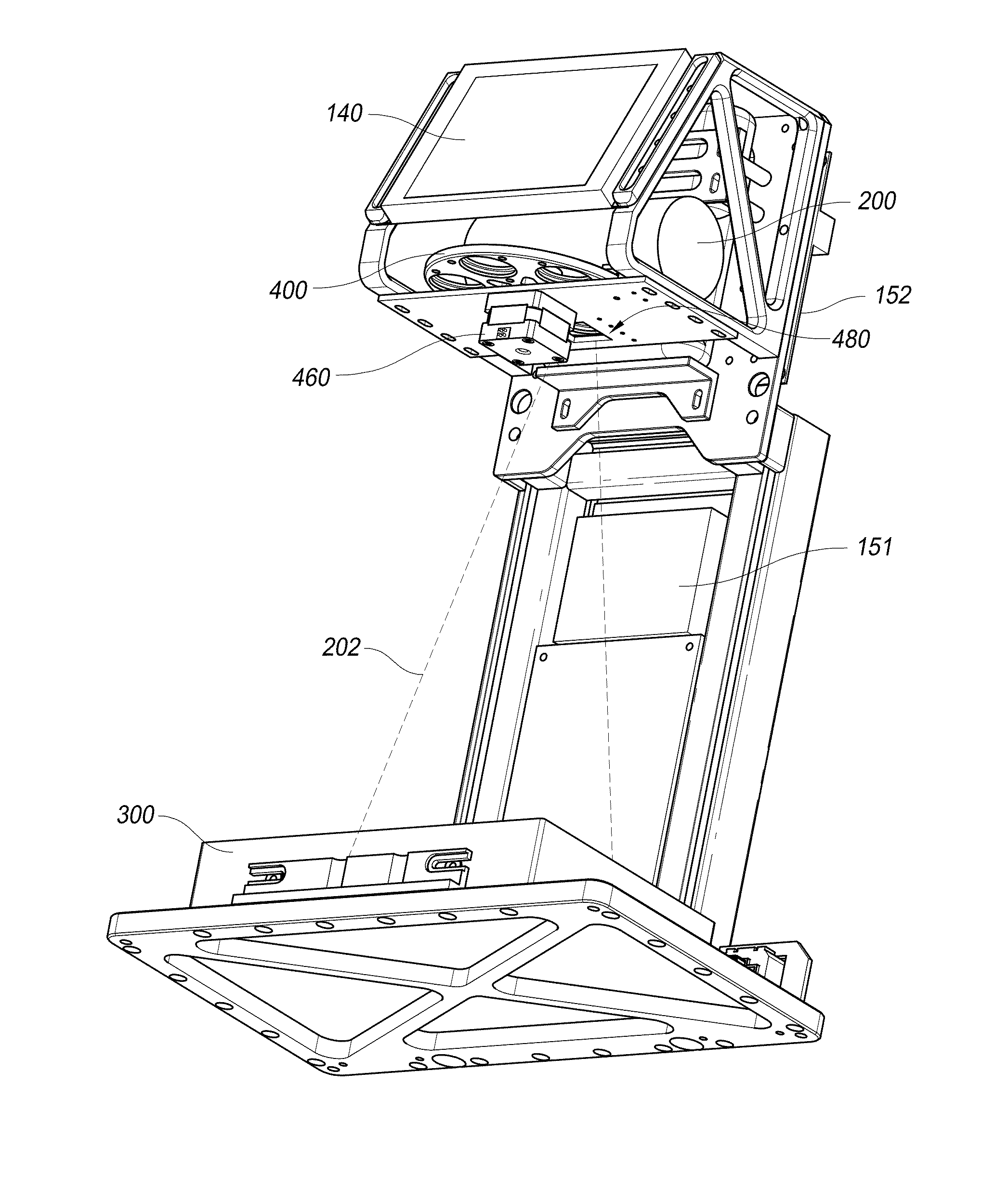
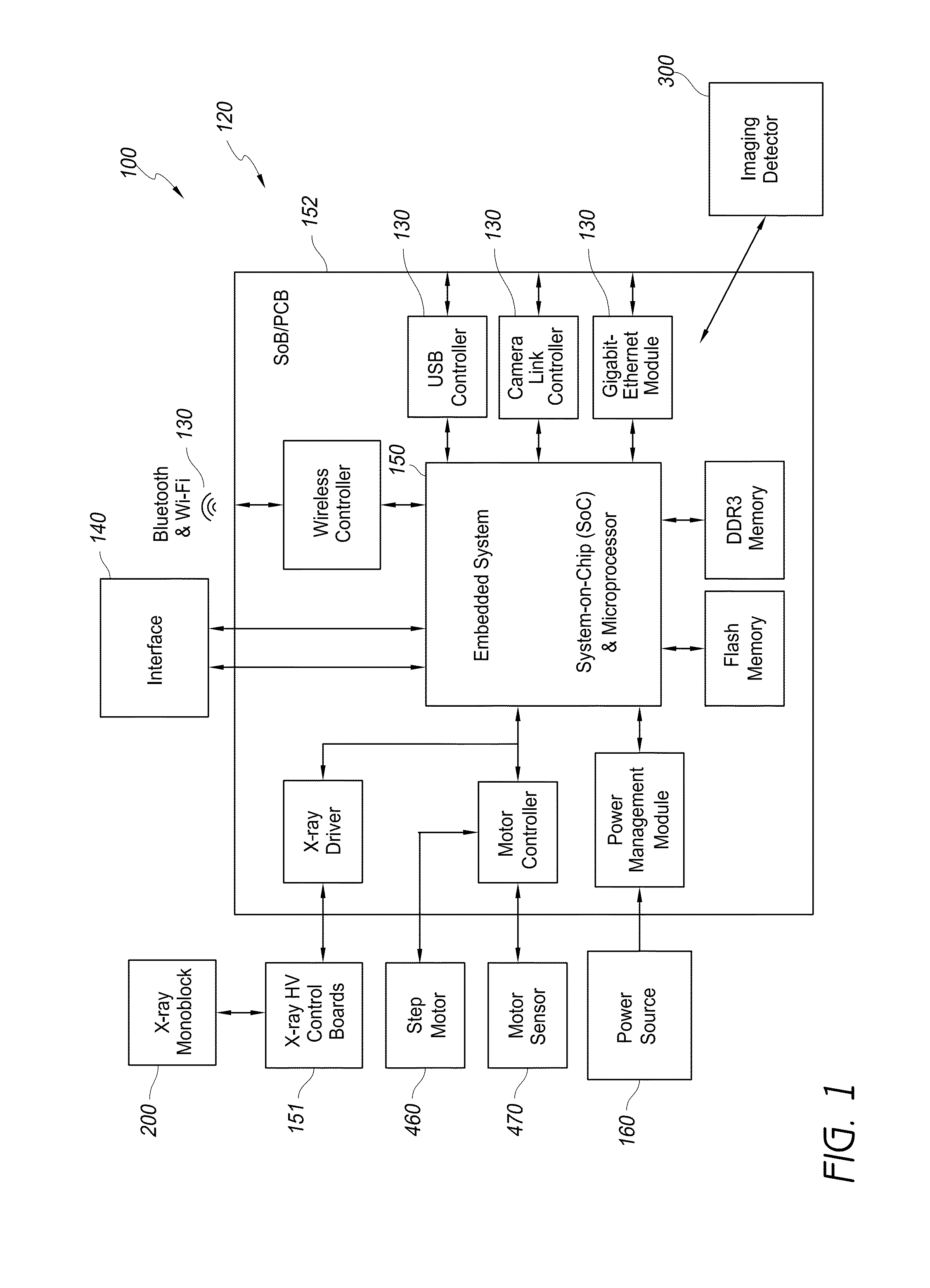
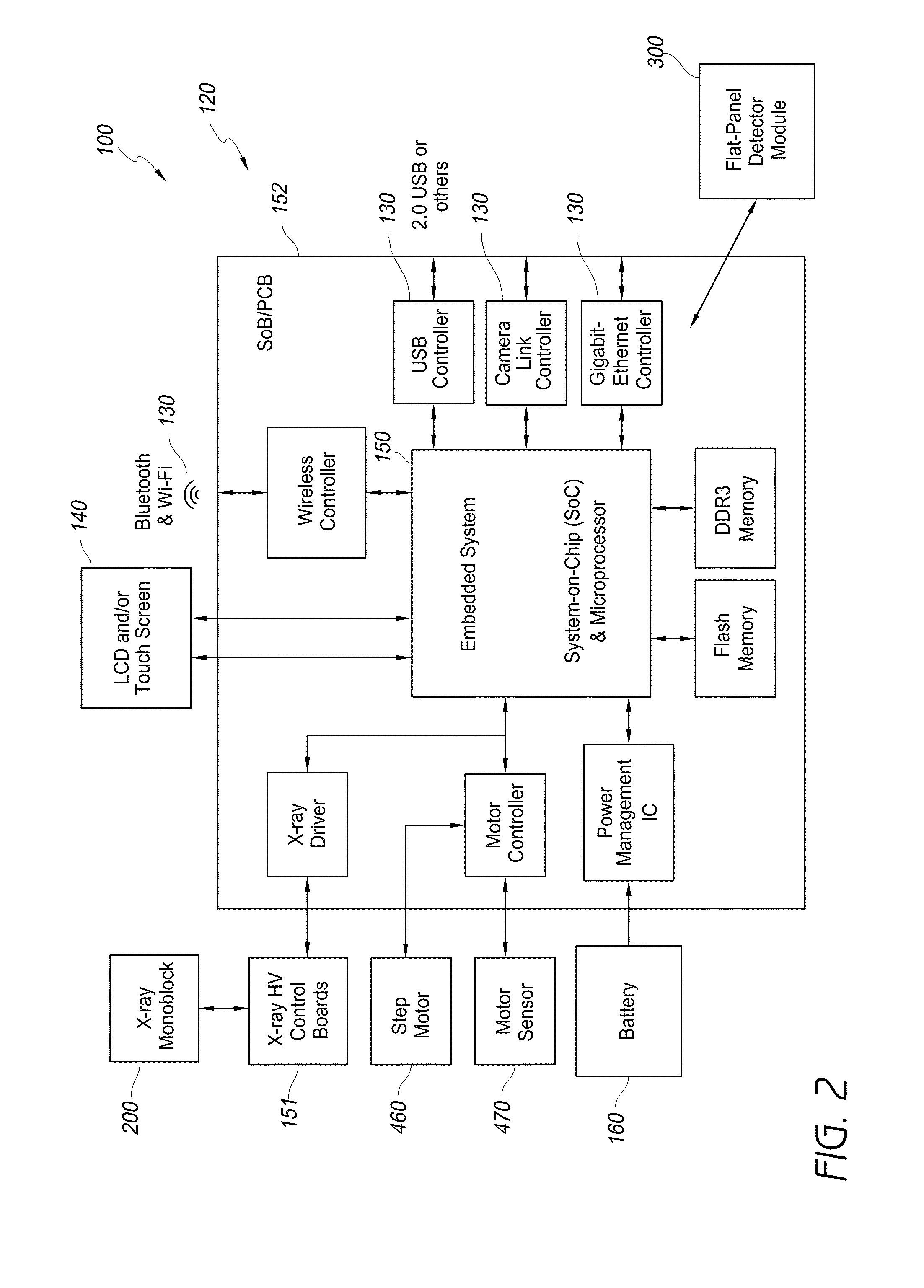
[0039]In various embodiments, an X-ray system 100 can be configured for various uses, improvements, and / or advantages over ...


PUM


Abstract

Devices, tools, systems and methods for X-ray bone density measurement and imaging for radiography, fluoroscopy and related procedures. Portable, efficient peripheral bone density measurement and/or high resolution imaging and/or small field digital radiography of bone and other tissue, including tissue in the peripheral skeletal system, such as the arm, forearm, leg, hand and/or foot.

Description

CROSS-REFERENCE TO RELATED APPLICATIONS[0001]This application claims the benefit of priority to U.S. Provisional Application No. 61 / 664,066, filed on Jun. 25, 2012, which is incorporated in its entirety by reference herein. Any and all priority claims identified in the Application Data Sheet, or any correction thereto, are hereby incorporated by reference under 37 CFR 1.57.BACKGROUND[0002]1. Field[0003]Embodiments of the present invention generally relate to devices, tools, systems and methods for X-ray bone density measurement and imaging for radiography, fluoroscopy and related procedures. More specifically, embodiments of the present invention relate to devices, tools, systems and methods for portable, efficient peripheral bone density measurement and / or high resolution imaging and / or small field digital radiography and / or fluoroscopy of bone and other tissue, including tissue in the peripheral skeletal system, such as arms, legs, hands and feet. In one embodiment, a system uses ...

Claims


Application Information

Patent Timeline
Patent Type & Authority Applications(United States)
IPC IPC(8): A61B6/00
CPCA61B6/4035A61B6/482A61B6/508A61B6/487A61B6/542A61B6/4042A61B6/461A61B6/467A61B6/505A61B6/563
Inventor MA, GEORGE W.
Owner MA GEORGE W
Why Eureka
Try Eureka