Method and Apparatus for Lifting and Transporting Exercise Equipment

a technology for lifting and transporting exercise equipment, applied in the field of lifting equipment, can solve the problems of difficulty and impracticality in performing service work on cardio equipment on the exercise floor, difficulty in one repair technician to move the equipment by himself or herself, etc., and achieve the effect of preventing the swinging of the exercise equipment during the transi

Inactive Publication Date: 2013-12-26
GOBERT KIM JASON JOSEPH
View PDF7 Cites 15 Cited by
  • Summary
  • Abstract
  • Description
  • Claims
  • Application Information

AI Technical Summary

Benefits of technology

[0013]Preferably there are provided supports for placement under the exercise equipment when lifted for lowering of the exercise equipment onto the supports to prevent swinging of the exercise equipment during transit.

Problems solved by technology

Performing service work on cardio equipment on the exercise floor is difficult and impractical, as there may be wires and tools scattered around, and the noise from the drill or vacuum may disturb the customers.
Repairs often require lubricant sprays and cleaning solutions, which could pose a problem to those with sensitivities to products with scents.
Also, the lighting on a gym floor is not ideal for working on small parts.
Ideally, the work should be done in a designated work area, but it can be difficult for one repair technician to move the equipment by himself or herself due to the weight, size and awkward shape of such equipment.
Off the shelf dollies or hand trucks are typically unsuitable to accommodate the bulky size and shape of such equipment, and additionally would require manual lifting or tipping of the heavy equipment, presenting notable risk of injury to the technician and / or damage to the equipment.
Off the shelf hoists intended for other equipment handling applications, for example engine hoists, are also unsuitable to address equipment handling needs in an exercise facility, for example due to the unsuitability for such equipment to access a particular machine from among a row of closely spaced machines in a common gym layout.

Method used


Image

  • Method and Apparatus for Lifting and Transporting Exercise Equipment
  • Method and Apparatus for Lifting and Transporting Exercise Equipment
  • Method and Apparatus for Lifting and Transporting Exercise Equipment

Examples


Embodiment Construction

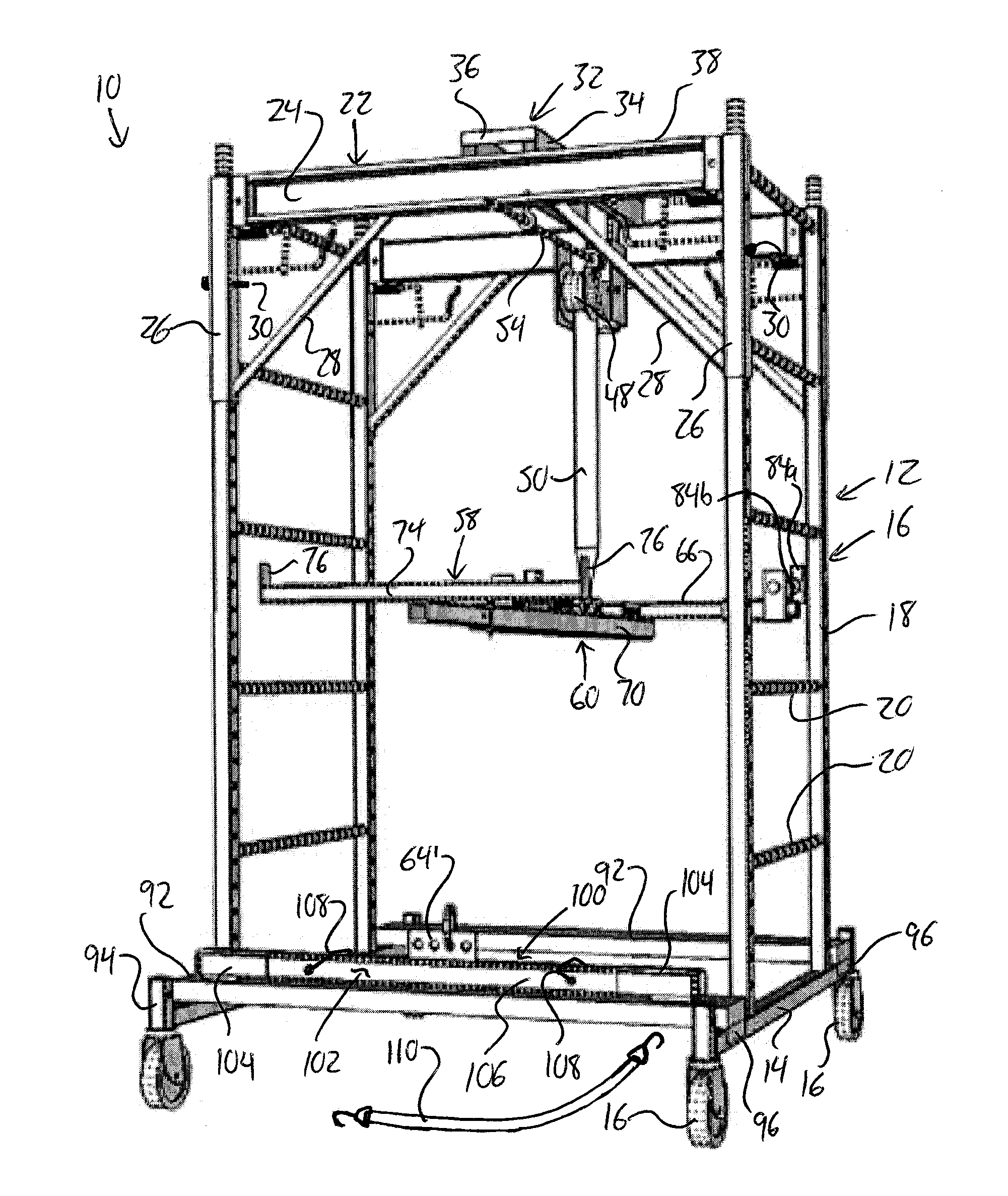
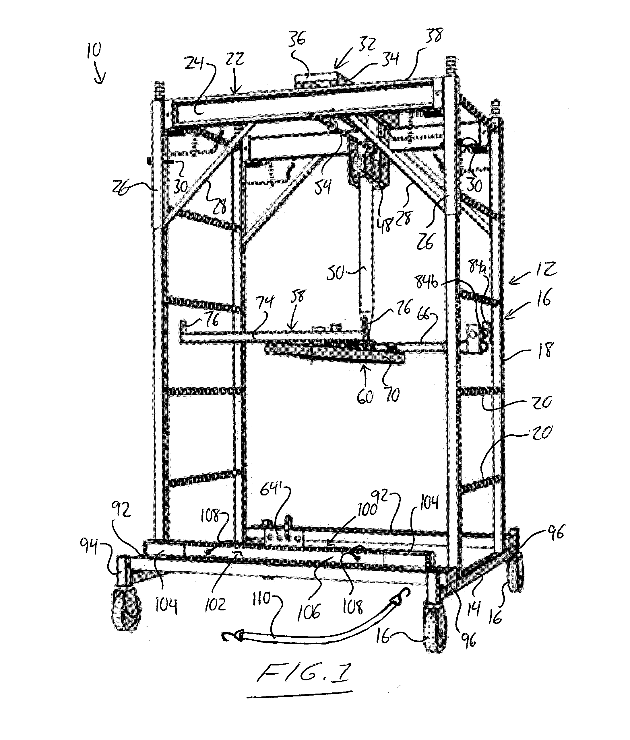
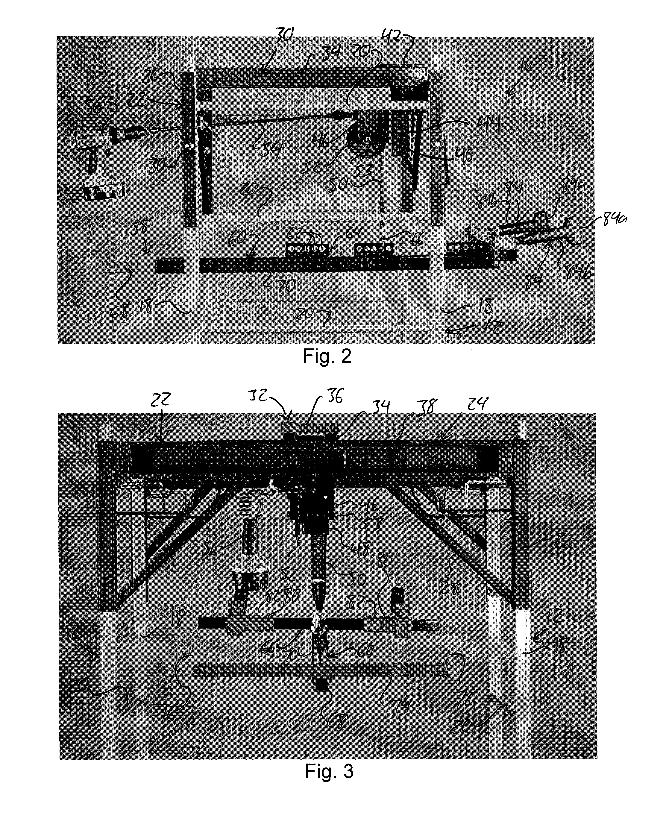
[0055]FIG. 1 shows an apparatus according to one embodiment of the present invention for lifting and transporting exercise equipment, including but not limited to treadmills, elliptical trainers, and other cardio-workout equipment. The structure of the illustrated apparatus is detailed herein as follows with particular reference to FIGS. 1 to 3.

[0056]The apparatus 10 features two side frames 12 that are horizontally spaced apart in a lateral direction of the apparatus. Each side frame 12 features an elongated horizontal base member 14 running linearly in a longitudinal direction of the apparatus that lies perpendicular to the aforementioned lateral direction. A respective caster wheel 16 is attached to the base member 14 adjacent each end thereof to rollably support the side frame 12. Centered on the length of the base member 14 is a generally ladder-shaped upright structure 16 featuring two vertically upright posts 18 spaced apart along the longitudinal direction, and horizontally ...


PUM


Abstract

An apparatus and method for lifting and transporting exercise equipment features use of a winch movably supported on a header spanning between a pair of wheeled side frames for adjustment of the winch position in two dimensions to account for varying center of gravity locations on different pieces of equipment to be lifted. The apparatus is rolled into a position straddling the equipment for lifting of same, at which time supports are laid across the space between the side frames for lowering of the equipment onto the supports for stable seated transport of the equipment on the supports by rolling of the wheeled apparatus. A single service technician can easily and safely remove a piece of equipment from the exercise floor to avoid disruption or hazard to gym members.

Description

[0001]This application claims benefit under 35 U.S.C. 119(e) of provisional application Ser. No. 61 / 663,786, filed Jun. 25, 2012.FIELD OF THE INVENTION[0002]The invention relates generally to lifting equipment, and more particularly to lifting equipment and methods adapted for lifting and transporting treadmills, elliptical machines or other exercise equipment of notable bulk and weight out, for example, out of a row of such equipment at an exercise facility.BACKGROUND OF THE INVENTION[0003]Many pieces of cardio equipment at a gym need regular maintenance. Performing service work on cardio equipment on the exercise floor is difficult and impractical, as there may be wires and tools scattered around, and the noise from the drill or vacuum may disturb the customers. Repairs often require lubricant sprays and cleaning solutions, which could pose a problem to those with sensitivities to products with scents. Also, the lighting on a gym floor is not ideal for working on small parts. Idea...

Claims


Application Information

Patent Timeline
Patent Type & Authority Applications(United States)
IPC IPC(8): B60P1/54
CPCB60P1/5438B66C5/02A63B71/0036A63B22/02A63B22/0605
Inventor GOBERT, KIM JASON JOSEPH
Owner GOBERT KIM JASON JOSEPH
Why Eureka
Try Eureka