Use of a fluorescent material to detect failure or deteriorated performance of a fluorometer

a technology of optical signal detector and fluorescent material, which is applied in the direction of fluorescence/phosphorescence, optical radiation measurement, spectrophotometry/monochromator, etc., can solve the problems of inability to detect, inability to repeatedly shut down the instrument, and inability to perform diagnostic errors

Active Publication Date: 2013-12-26
GEN PROBE INC
View PDF1 Cites 24 Cited by
  • Summary
  • Abstract
  • Description
  • Claims
  • Application Information

AI Technical Summary

Benefits of technology

[0009]The present invention provides systems and methods for self-checking an optical signal detector, such as a fluorometer, to detect failure or deteriorated performance of the signal detector, wherein self-checking can...

Problems solved by technology

A malfunction (device failure and/or deteriorated performance) by a fluorometer during operation of the instrument will cause errors in the fluorometric readings generated by that fluorometer and thereby cause errors in the diagnostic results.
Such malfunctions may be due to mechanical and/or electrical failures that occur during operation of the fluorom...

Method used


Image

  • Use of a fluorescent material to detect failure or deteriorated performance of a fluorometer
  • Use of a fluorescent material to detect failure or deteriorated performance of a fluorometer
  • Use of a fluorescent material to detect failure or deteriorated performance of a fluorometer

Examples


Embodiment Construction

[0062]Multiple Receptacle Devices

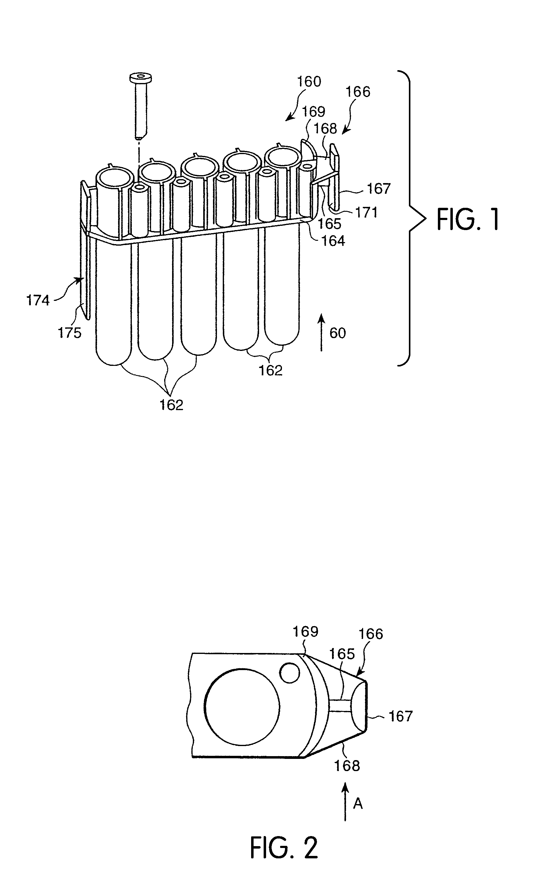
[0063]Referring to FIG. 1, a reaction receptacle in the form of a multiple receptacle device (“MRD”) 160 comprises a plurality of individual receptacle vessels, or reaction tubes, 162, preferably five. The receptacle vessels 162, preferably in the form of cylindrical tubes with open top ends and closed bottom ends, are connected to one another by a connecting rib structure 164 which defines a downwardly facing shoulder extending longitudinally along either side of the MRD 160.

[0064]The MRD 160 is preferably formed from injection molded polypropylene, such as those sold by Montell Polyolefins, of Wilmington, Del., product number PD701NW or Huntsman, product number P5M6K-048. In an alternative embodiment, the receptacle vessels 162 of the MRD are releasably fixed with respect to each other by means such as, for example, a sample tube rack.

[0065]An arcuate shield structure 169 is provided at one end of the MRD 160. An MRD manipulating structure 166 exte...


PUM


Abstract

A System and method for self-checking a fluorometer for failure or deteriorated performance includes fluorescent reference standards mounted on a support to move with respect to one or more fixed fluorometers. The intensity of the fluorescent emission of the fluorescent reference standard is initially measured with the fluorometer, and, after a prescribed interval of usage of the fluorometer, a test measurement of the intensity of the fluorescent emission of the fluorescent standard is taken with the fluorometer. The test measurement is compared to the initial measurement, and failure or deteriorated performance of the fluorometer is determined based on a deviation of the test measurement from the initial measurement.

Description

CROSS-REFERENCE TO RELATED APPLICATION[0001]This application claims the benefit under 35 U.S.C. §119(e) of U.S. Provisional Application No. 61 / 659,590, filed Jun. 14, 2012, the disclosure of which is hereby incorporated by reference.BACKGROUND[0002]1. Field of the Invention[0003]The present invention relates to systems and methods for detecting failure or deteriorated performance of an optical signal detector, such as a fluorometer, and, in particular, systems and methods employing fluorescent materials carried on an instrument within which the fluorometer is employed to detect fluorescent signals emitted by sample materials.[0004]2. Background of The Invention[0005]None of the references described or referred to herein are admitted to be prior art to the claimed invention.[0006]Diagnostic assays are widely used in clinical diagnosis and health science research to detect or quantify the presence or amount of biological antigens, cell abnormalities, disease states, and disease-associ...

Claims


Application Information

Patent Timeline
IPC IPC(8): G01N21/64
CPCG01N21/645G01N21/276
Inventor LI, HAITAOOPALSKY, DAVIDHEINZ, R. ERICHAGEN, NORBERT D.
Owner GEN PROBE INC
Why Eureka
Try Eureka