
Openable Roof Window

a technology of roof window and movable window panel, which is applied in the direction of door/window fittings, wing accessories, wing arrangements, etc., can solve the problems of insufficient difficult to achieve sufficient support stiffness and the closing mechanism disclosed in the foregoing prior art documents does not contribute to the increase in the strength of the movable window panel. , to achieve the effect of simple and reliable structure,

Active Publication Date: 2014-01-02
YACHIYO IND CO LTD
View PDF10 Cites 6 Cited by
  • Summary
  • Abstract
  • Description
  • Claims
  • Application Information

AI Technical Summary

Benefits of technology

The present invention provides an openable roof window with a movable window panel that is tiltable and slidable. This improves the support stiffness and strength of the movable window panel.

Problems solved by technology

Many roof windows are of the type that cannot be opened and closed since they are often installed at locations that cannot be easily accessed.
However, in the conventional openable roof windows, the support stiffness of the movable window panel is not sufficient when the roof window is open.
Specifically, in the openable roof window disclosed in JP 63-27656A, the movable window panel is supported only by the pair of links each consisting of an elongated rod member connected to the base frame and the movable window panel at the end portions thereof pivotably or slidably, and therefore, it is difficult to achieve sufficient support stiffness of the movable window panel.
Further, the opening and closing mechanisms disclosed in the foregoing prior art documents do not contribute to increase in the strength of the movable window panel.
Moreover, the openable roof windows disclosed in these prior art documents are not configured to allow the movable window panel to slide relative to the base frame.

Method used


Image

  • Openable Roof Window
  • Openable Roof Window
  • Openable Roof Window

Examples


Embodiment Construction

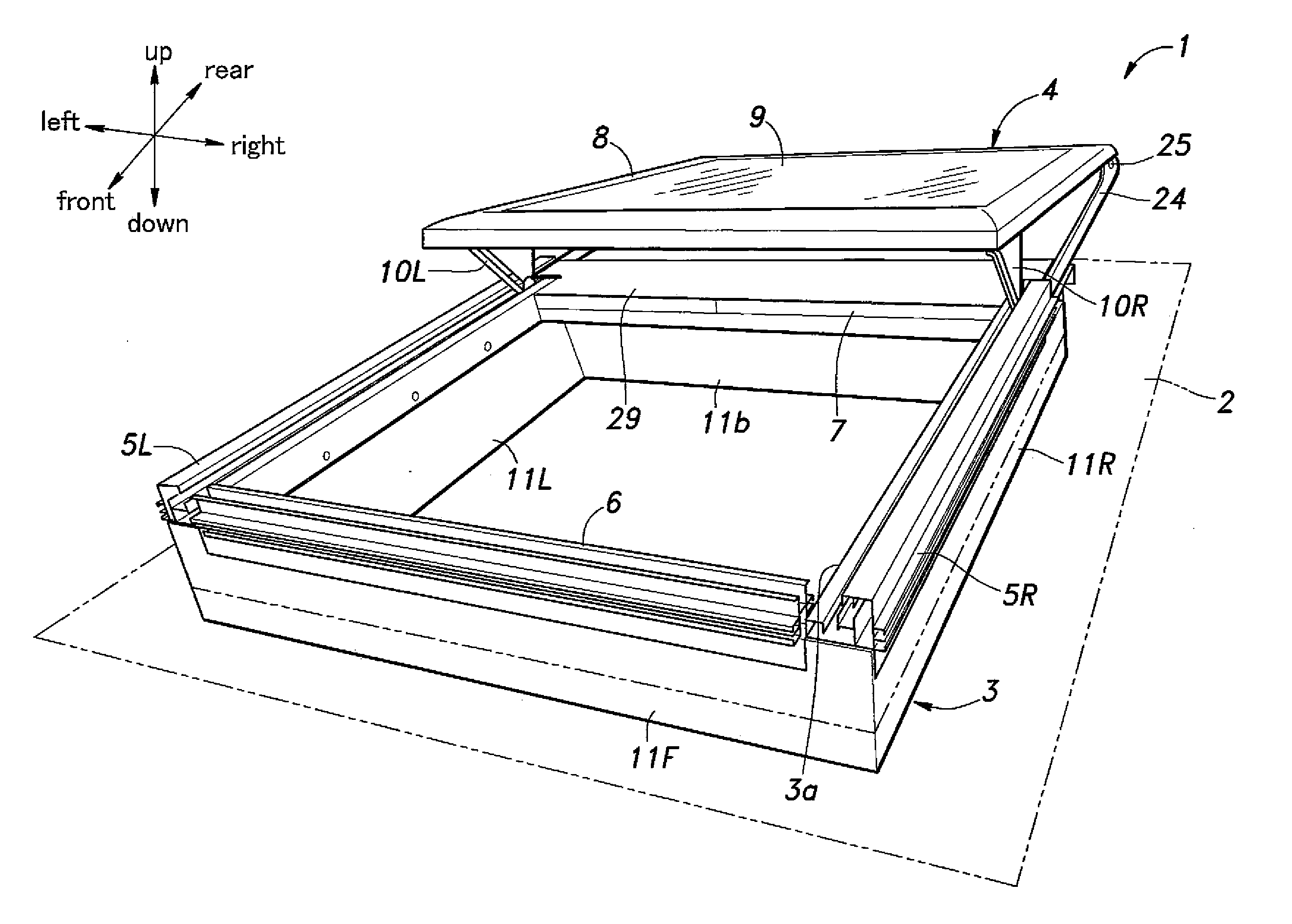
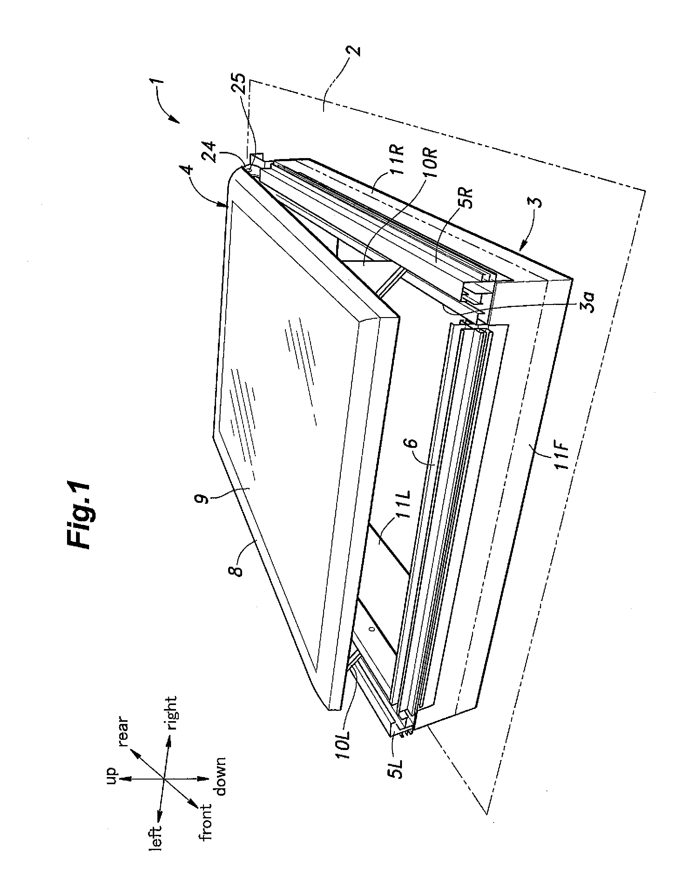
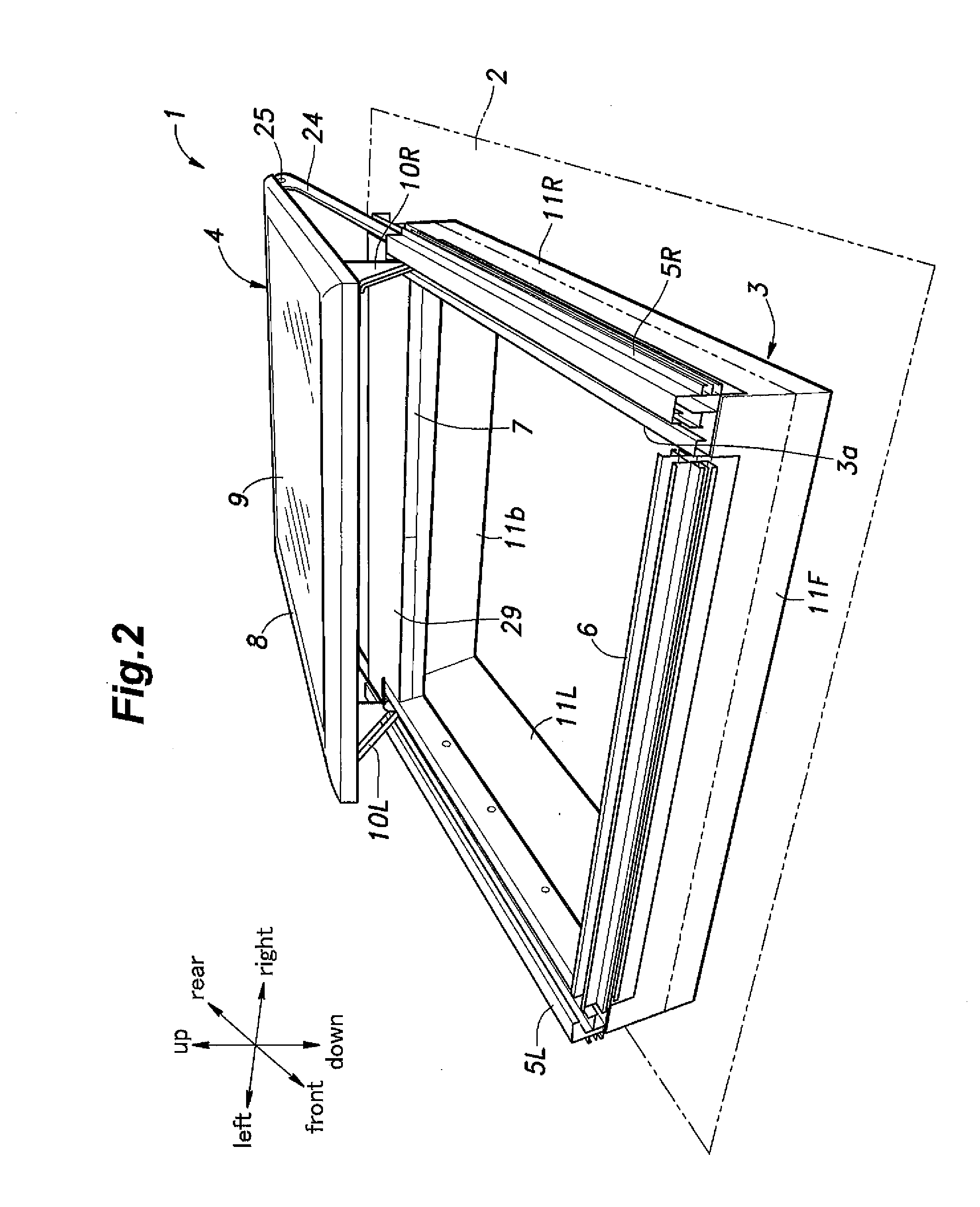
[0033]Now, with reference to the appended drawings, description will be made of an embodiment of the present invention, in which an openable roof window (simply referred to as a roof window 1 hereinafter) is mounted to a roof 2 of a house. It is to be noted that some component parts or portions such as those provided in a pair on left and right sides of the roof window, on front and rear (or back) sides of the roof window, or on inner and outer sides of a certain component part, will be denoted by reference signs including a common numeral suffixed with letters, such as “L” and “R” indicating “left” and “right,” respectively, “F” and “B” indicating “front” and “back,” respectively, or “i” and “o” indicating “inner” and “outer,” respectively. For example, a pair of guide rails provided on either side of the roof window will be denoted by reference signs 5L (left guide rail) and 5R (right guide rail), respectively, and a pair of inner and outer slider guide grooves formed in each guid...


PUM


Abstract

An openable roof window includes: a window panel configured to be slidable along a guide rail to selectively open and close an opening in a roof and tiltable relative to a base frame; a slider having a pin and driven by a drive device to slide along the guide rail; an engagement structure that selectively engages the slider with the window panel such that they are unmovable relative to each other in a direction along the guide rail; and a stay fixedly secured to the window panel and having a cam groove formed therein, the cam groove engaging the pin of the slider and having a shape defined such that, when the engagement structure does not engage the slider with the window panel, the window panel is caused to tilt as the slider moves relative to the stay as a result of sliding of the slider along the guide rail.

Description

CROSS-REFERENCE TO RELATED APPLICATIONS[0001]This application claims the priority of Japanese Patent Application No. 2012-144639, filed in the Japanese Patent Office on Jun. 27, 2012, the disclosure of which is hereby incorporated by reference herein in its entirety for all purposes.TECHNICAL FIELD[0002]The present invention relates to an openable roof window configured to be mounted on the roof of a building.BACKGROUND OF THE INVENTION[0003]Some houses are provided with a roof window (may also be referred to as a skylight) for admitting sunlight. Many roof windows are of the type that cannot be opened and closed since they are often installed at locations that cannot be easily accessed. However, some roof windows are designed to be openable for ventilation, for example. Such an openable roof window may be opened and closed manually or may be driven electrically by an electric drive device in response to an operation performed by a user on an operation unit connected to the drive de...

Claims


Application Information

Patent Timeline
IPC IPC(8): E06B3/50
CPCE06B3/5054E04D13/0357E05Y2900/154E05Y2201/638E05F15/638
Inventor UEHARA, TATSUAKIMIHASHI, AYUMI
Owner YACHIYO IND CO LTD
Learn More