
Traction control system for vehicle

a technology for traction control and vehicles, applied in vehicle components, electric control, propulsion unit safety devices, etc., can solve problems such as deteriorating the convergence of driving slips, and achieve the effects of improving the convergence of engine output torque, facilitating convergent engine output torque, and improving engine output torque convergen

Inactive Publication Date: 2014-01-02
HONDA MOTOR CO LTD
View PDF4 Cites 14 Cited by
  • Summary
  • Abstract
  • Description
  • Claims
  • Application Information

AI Technical Summary

Benefits of technology

The present invention provides a traction control system for a vehicle that improves the convergence of driving slip. This is achieved by calculating the average output torque of the engine during a fuel cut pattern and correcting the remaining fuel cut pattern by comparison of the average output torque and the target torque. The fuel cut pattern is also corrected based on the already-performed fuel cut to make it easier to converge the output torque into the target torque, even if the rider operates the throttle grip during the fuel cut pattern. The output torque is calculated by the engine speed and the throttle opening at the time of fuel injection of the cylinders during the fuel cut process. The ratio of the target torque to the output torque is evaluated to determine the optimum fuel cut pattern for convergence into the target torque. The unit section is the section including the fuel injection process which is a positive even multiple of the number of cylinders the engine has, and the average output torque predicting means predicts the average output torque at the stage in which the majority of the unit section ends to improve the convergence with respect to the target torque.

Problems solved by technology

Therefore, the unit section of the fuel cut pattern is divided into small sections, which thereby deteriorates the convergence of the driving slip.

Method used


Image

  • Traction control system for vehicle
  • Traction control system for vehicle
  • Traction control system for vehicle

Examples


Embodiment Construction

[0023]Embodiments of a vehicle and a traction control system for a vehicle according to the present invention will be described in detail hereinafter with reference to the accompanying drawings.

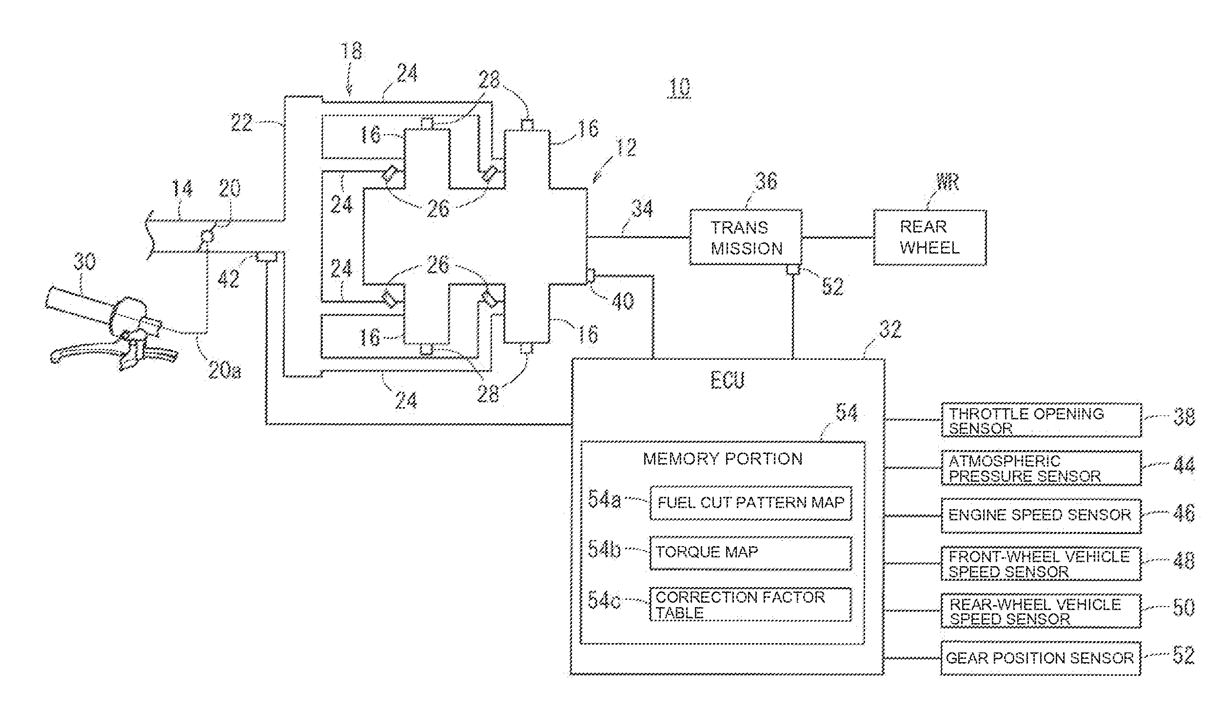
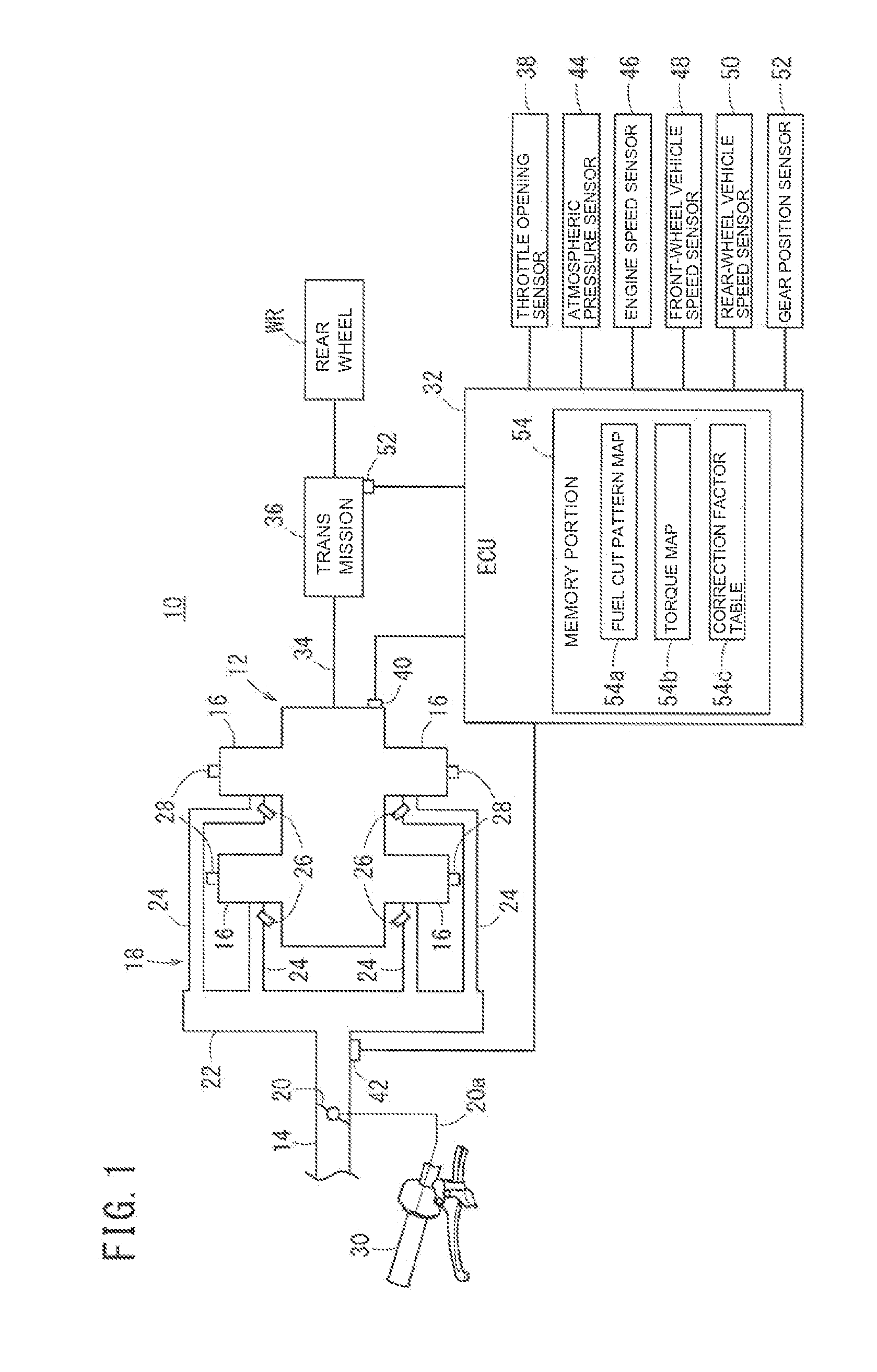
[0024]FIG. 1 is the electric schematic configuration diagram of a traction control system 10 for a vehicle mounted on, in this example, a motorcycle.

[0025]A vehicle can have a four-cylinder engine 12, a main intake pipe 14, the upstream side of which a not-shown air cleaner is connected to, and an intake manifold 18 which connects the main intake pipe 14 and each of the cylinders 16 of the engine 12. The main intake pipe 14 is provided with a throttle valve 20 for adjusting the amount of air which is taken in the engine 12. The intake manifold 18 has a surge tank 22 and a plurality of sub-intake pipes 24, and the plurality of sub-intake pipes 24 are connected to a not-shown combustion chamber of each of the cylinders 16.

[0026]Each of the sub-intake pipes 24 is provided with a fuel injection e...


PUM


Abstract

A vehicle includes an engine, a slip ratio calculating unit, a target torque calculating unit, a fuel cut pattern determining unit, and a fuel cut control unit. The vehicle also includes a traction control system which includes an average output torque predicting unit and a fuel cut pattern correcting unit configured to correct the remaining fuel cut pattern during a unit section by judging the overage and shortage of generation of an output torque of the engine by comparison of the average output torque and the target torque.

Description

BACKGROUND[0001]1. Field[0002]The present invention relates to a traction control system for a vehicle which reduces the driving force depending on the slip ratio of the front and rear wheels.[0003]2. Description of the Related Art[0004]Patent Document 1 (Japanese Laid-Open Patent Publication No. H6-146944) describes that the output of an engine is generated in such a way as to determine an output reduction request signal depending on the size of the slip condition of driving wheels and to perform a fuel cut based on a fuel cut pattern depending on the output reduction request signal. The number of cylinders in which the fuel supply is cut is different by fuel cut pattern, and the requested number of fuel cut cylinders for the injection calculation, which is executed in each injection process of each of the cylinders, is updated.[0005]However, when the fuel cut pattern is updated, the initial fuel cut pattern is forced to end in the middle of a unit section, and the fuel cut pattern...

Claims


Application Information

Patent Timeline
Patent Type & Authority Applications(United States)
IPC IPC(8): F02D41/30
CPCF02D41/30B60W30/18172F02D41/0087F02D2041/1412F02D2200/1004F02D2200/1006F02D2250/18B60K28/16F02D41/123B60T8/175
Inventor NAKAMURA, MASANORIABE, TAKERUKATO, TATSURO
Owner HONDA MOTOR CO LTD
Learn More