

Method of forming a capacitor structure, and a silicon etching liquid used in this method
a technology of etching liquid and capacitor, which is applied in the field of forming a capacitor structure and a silicon etching liquid used in this method, can solve the problems of difficult processing, difficult to cope with the production of capacitors in terms of microprocessing technology, and the process itself of forming a fine cylinder structure or a bore therein by processing with high accuracy, etc., to achieve accurate and efficient removal, excellent operating effect, and good balan
Inactive Publication Date: 2014-01-02
FUJIFILM CORP
View PDF10 Cites 16 Cited by
- Summary
- Abstract
- Description
- Claims
- Application Information
AI Technical Summary
Benefits of technology
[0008]According to the present invention, the material of amorphous silicon, polycrystalline silicon or the like in an area where a capacitor structure having concavities and convexities can be accurately and efficiently removed, and etching can be achieved in a well-balanced manner between the center and the edges of a wafer on which a number of capacitor structures are formed. Furthermore, the present invention provides an excellent operating effect that if necessary, the present invention can even cope with a capacitor structure constituted of electrodes having a cylin
Problems solved by technology
In order to satisfy these two requirements, the depth of the cylinder bore is further deepened, so that it is becoming more difficult to cope with the production of capacitors in terms of microprocessing technology.
As such, attempts have been made to control the aspect ratio of the capacitor structure, but the process itself of forming a fine cylinder structure or a bore therein by processing with high accuracy is not that simple.
Particularly, th
Method used
View moreImage
Smart ImageViewing Examples

Examples
 PUM
 Abstract
A method of forming a capacitor structure, which comprises: applying a silicon etching liquid which contains an alkali compound and a hydroxylamine compound in combination, with the pH adjusted to 11 or more, to a polycrystalline silicon film or an amorphous silicon film, removing a part or all of the polycrystalline silicon film or amorphous silicon film, and forming concave and convex shapes that constitute a capacitor.
Description
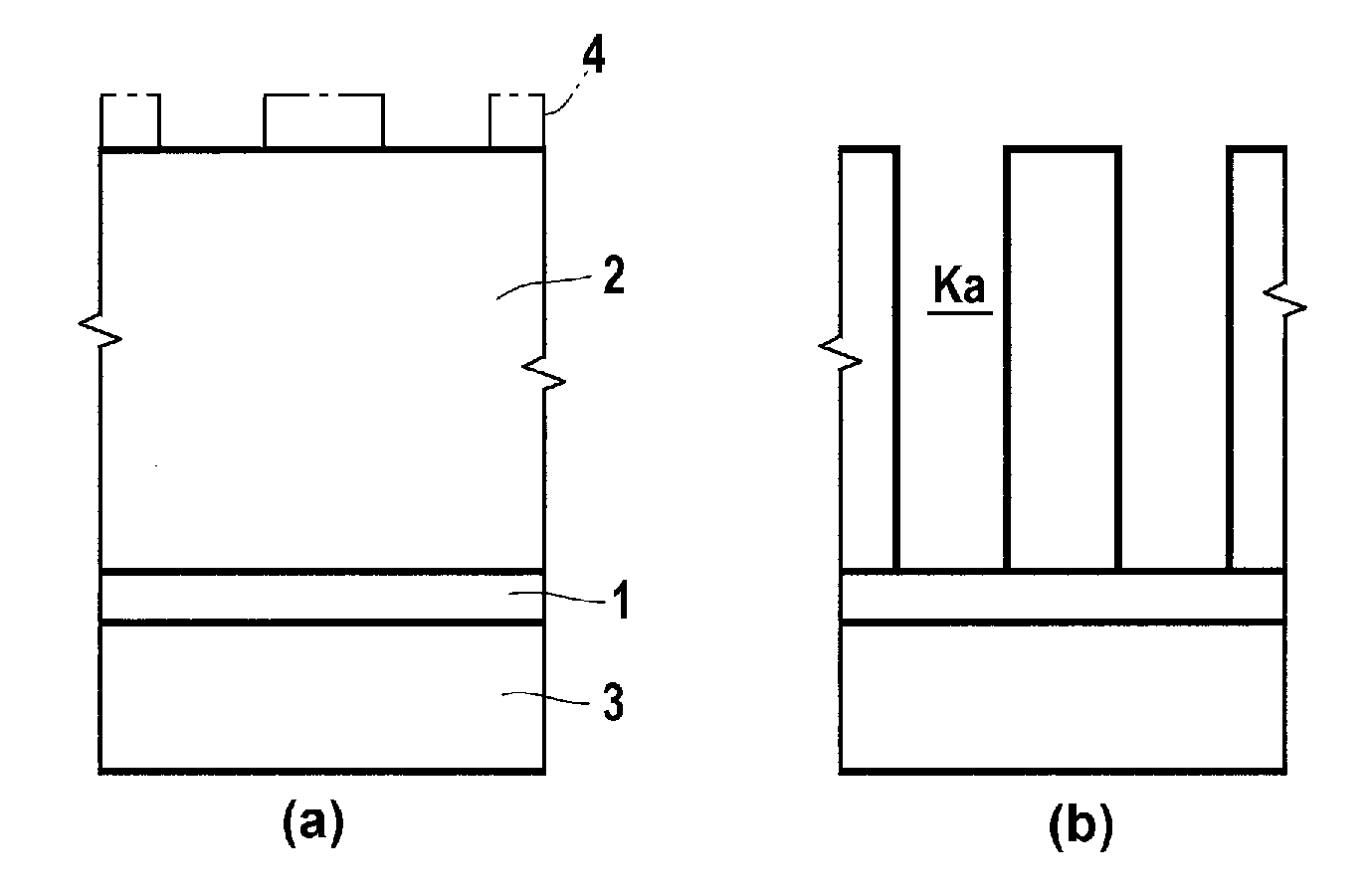
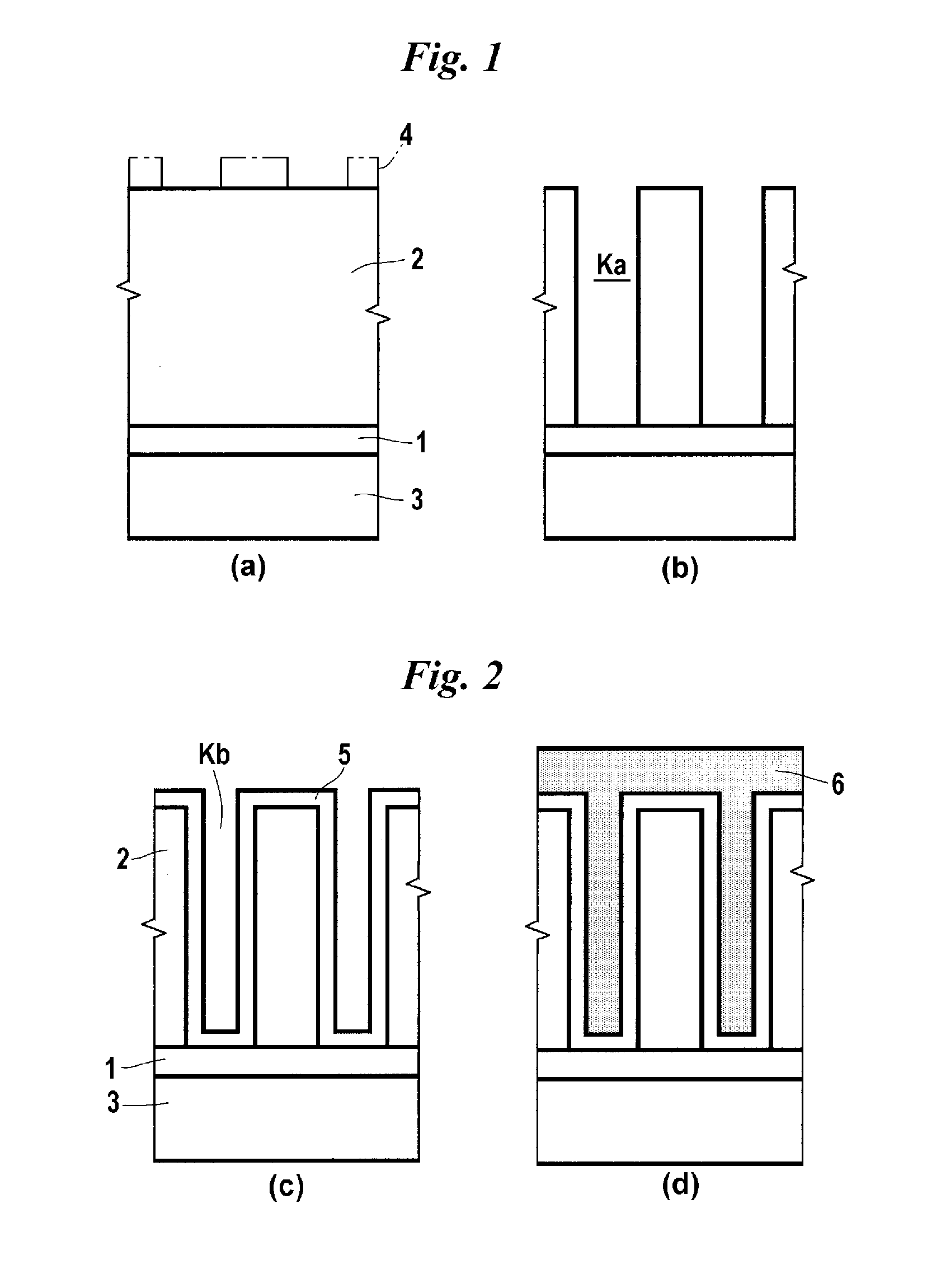
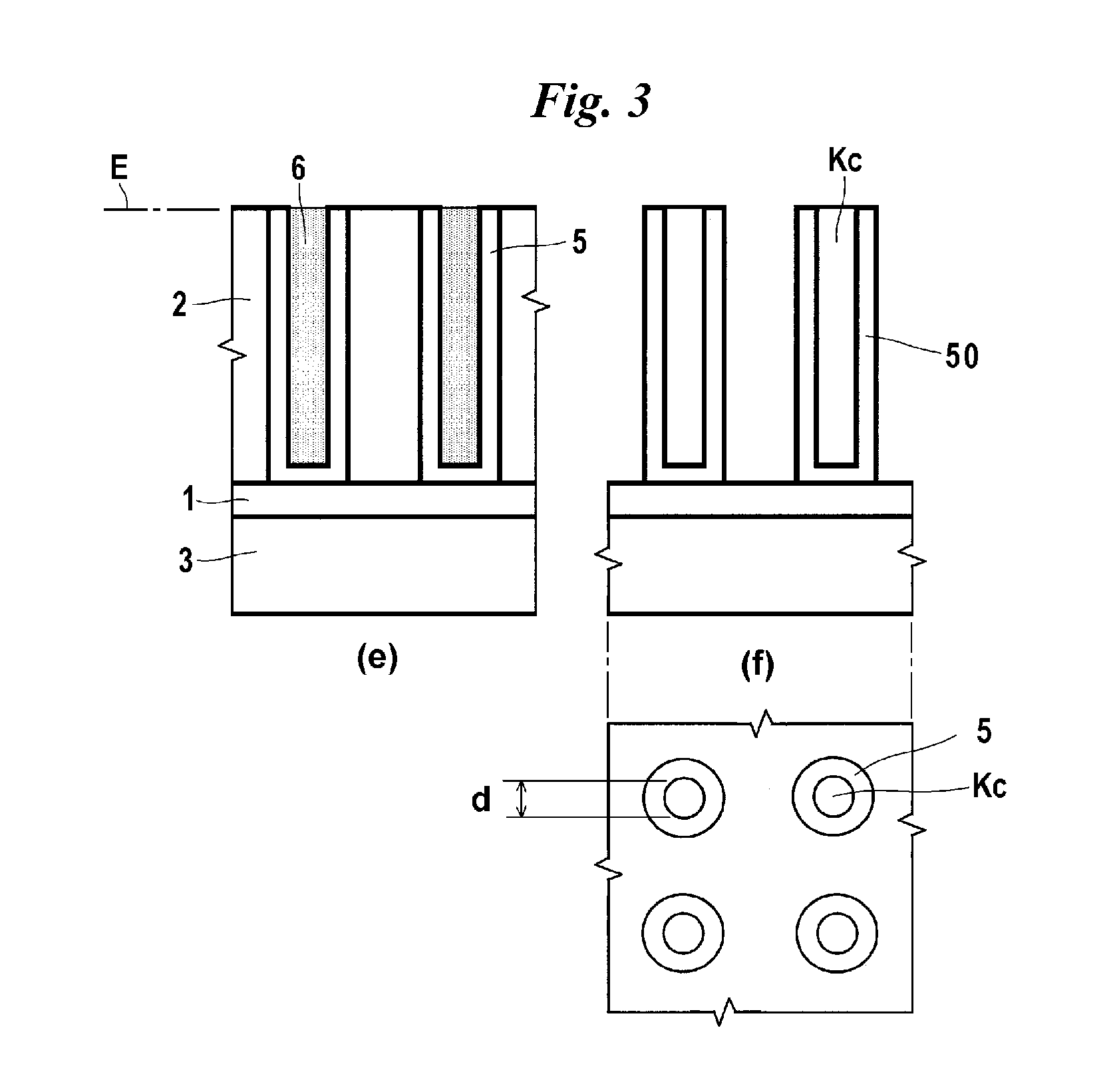
TECHNICAL FIELD[0001]The present invention relates to a method of forming a capacitor structure, and a silicon etching liquid used in this method.BACKGROUND ART[0002]A concave type structure has been conventionally employed for the capacitor structure in a dynamic random access memory (DRAM). In this structure, a lower electrode film is formed inside a cylinder bore, and only the inner surface is made to function as an electrode. According to this structure, the area occupied by the capacitor can be certainly made small, but the diameter of the cylinder bore is also necessarily decreased. On the other hand, it is necessary to secure the capacitance needed for the device operation of the DRAM. In order to satisfy these two requirements, the depth of the cylinder bore is further deepened, so that it is becoming more difficult to cope with the production of capacitors in terms of microprocessing technology. In view of such circumstances, there has been suggested a crown type capacitor ...
Claims
Login to View More Application Information
Patent Timeline
 IPC IPC(8): H01G13/00C09K13/02C09K13/00
CPCH01G13/00C09K13/00C09K13/02H01L21/02068H01L21/32134H01L28/92H01L21/308H01L21/306H10B99/00H10B12/00
InventorMIZUTANI, ATSUSHIINABA, TADASHIKOYAMA, AKIKO
OwnerFUJIFILM CORP