Unlock instant, AI-driven research and patent intelligence for your innovation.

Server memory cooling apparatus

Active Publication Date: 2014-01-02
ASETEK DANMARK
View PDF49 Cites 11 Cited by
  • Summary
  • Abstract
  • Description
  • Claims
  • Application Information

AI Technical Summary

Benefits of technology

The patent describes a cooling system for in-line memory modules that helps maintain the temperature of the memory module within a proper range for proper functioning. The system includes a heat spreader and a liquid-cooler block, which are in thermal communication with each other. The heat spreader attaches to the memory module and transfers heat to the liquid-cooler block through a heat-conducting cold plate. The liquid-cooler block cools the heat using a circulating cooling liquid. The system can fit in the space between two different heights of DIMMs, making it easy to access and replace the memory module for maintenance. The technical effects of the system are reduced temperatures for optimized memory performance and simplified maintenance.

Problems solved by technology

While the problem of heat removal from IC devices is an old one, this problem has increased in recent years due to greater numbers of transistors that are packed into a single IC device while reducing the physical size of the device.
Increasing the number of transistors compacted into a smaller area results in a greater concentration of heat that must he removed from that smaller area.
In contrast, there are no standards for the space surrounding DIMMs in a computer system.
If a DIMM becomes too warm, for example above a Tcase by a defined threshold, such as 85 degrees Celsius, data bits are at a higher risk of corruption.
These systems require relatively large amounts of space and prevent compactness in overall device or system design.
Disadvantageously, air-cooling systems generate a great deal of noise, are energy inefficient, and are susceptible to mechanical failures.
In addition, the density of components in current systems obstructs the flow of air, reducing the heat-removing efficacy of such cooling systems.

Method used


Image

  • Server memory cooling apparatus
  • Server memory cooling apparatus
  • Server memory cooling apparatus

Examples


Embodiment Construction

)

[0027]For simplicity and clarity of illustration, reference numerals may be repeated among the figures to indicate corresponding or analogous elements. Also, similarly-named elements perform similar functions and are similarly designed, unless specified otherwise. Numerous details are set forth to provide an understanding of the embodiments described herein. The embodiments may be practiced without these details. In other instances, well-known methods, procedures, and components have not been described in detail to avoid obscuring the embodiments described. The description is not to be considered as limited to the scope of the embodiments described herein.

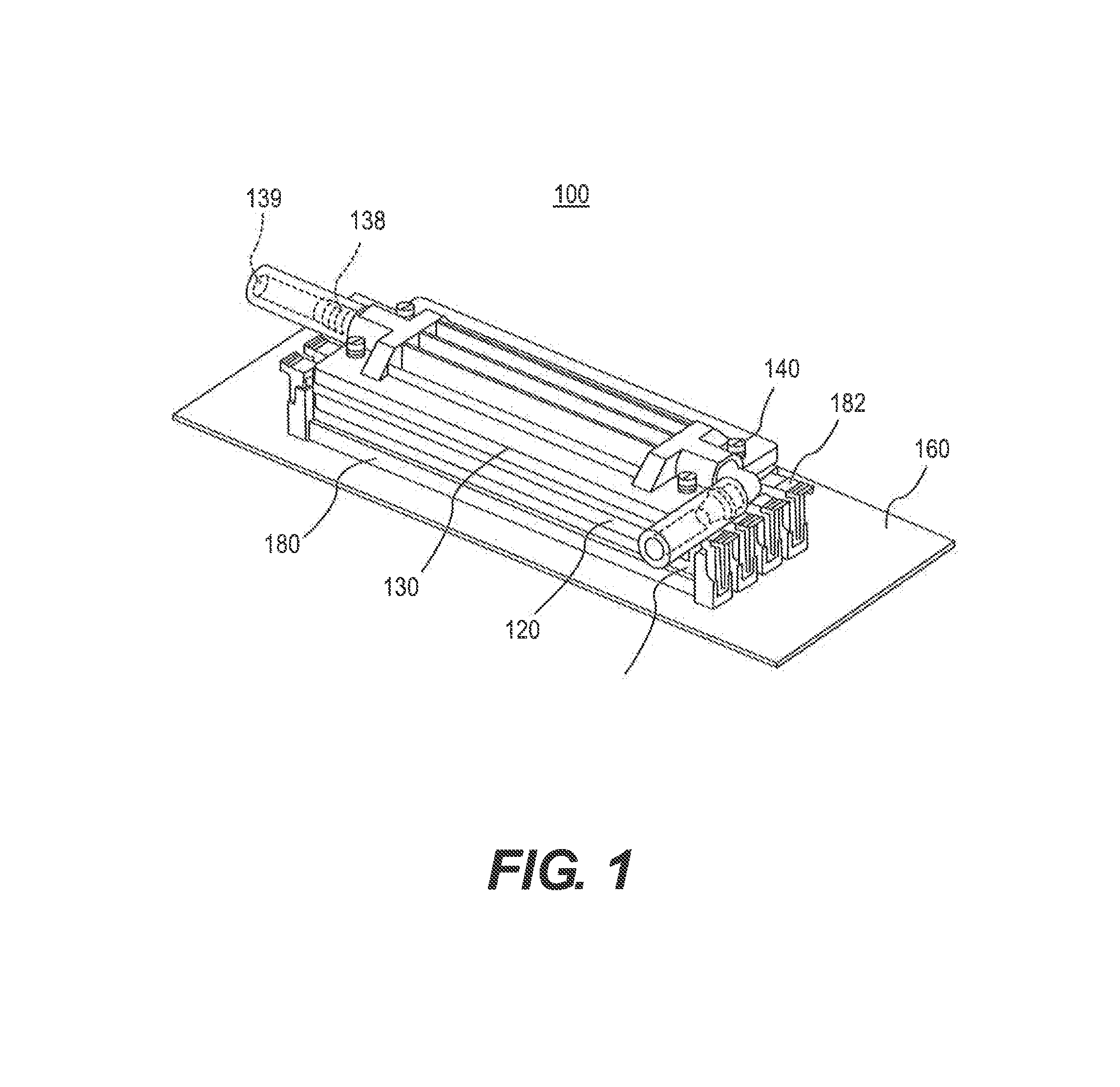
[0028]FIG. 1 is a perspective view of a thermal management system 100 in accordance with one embodiment of this disclosure. System 100 comprises in-line memory modules 110, heat spreader 120, liquid-cooler block 130, and securing mechanism 140. In-line memory module 110 connects to printed circuit board 160 via in-line memory modu...


PUM


Abstract

A system to aid in cooling an in-line memory module may include a heat spreader including a channel to accommodate the in-line memory module, thermal interface material, and a liquid-cooler block including a heat-conducting cold plate and an internal liquid channel filled with circulating cooling liquid. Also disclosed are systems employing tubes to convey cooling fluid.

Description

BACKGROUND OF THE INVENTION[0001]A. Field of the Invention[0002]The present disclosure is related generally to liquid cooling systems for cooling heat-generating components of a computer, server or other data processing devices and systems.[0003]B. Description of the Prior Art[0004]Electronic systems, such as, for example, computer systems include several integrated circuit (IC) devices that generate heat during operation. For effective operation of the computer system, the temperature of the IC devices has to be maintained within acceptable limits. While the problem of heat removal from IC devices is an old one, this problem has increased in recent years due to greater numbers of transistors that are packed into a single IC device while reducing the physical size of the device. Increasing the number of transistors compacted into a smaller area results in a greater concentration of heat that must he removed from that smaller area. Bundling multiple computer systems together, such as...

Claims


Application Information

Patent Timeline
IPC IPC(8): G06F1/20
CPCG06F1/20G06F2200/201H01L2924/0002H01L2924/00F28D15/00H01L23/473H05K7/20772H05K7/20254
Inventor BERK, TODDERIKSEN, ANDRE S.
Owner ASETEK DANMARK