Bidirectional dc-dc converter

a dc-dc converter and bi-directional technology, applied in the direction of dc-dc conversion, power conversion systems, instruments, etc., can solve the problems of asymmetric voltage sharing of power semiconductors, and achieve the effect of few losses

Active Publication Date: 2014-01-02
FLEXIBLE ELEKTRISCHE NETZE FEN GMBH
View PDF6 Cites 32 Cited by
  • Summary
  • Abstract
  • Description
  • Claims
  • Application Information

AI Technical Summary

Benefits of technology

[0008]One objective of the present invention is to put forward a bidirectional DC-DC converte

Problems solved by technology

Without additional measures, the voltage sharing of

Method used


Image

  • Bidirectional dc-dc converter
  • Bidirectional dc-dc converter
  • Bidirectional dc-dc converter

Examples


Embodiment Construction

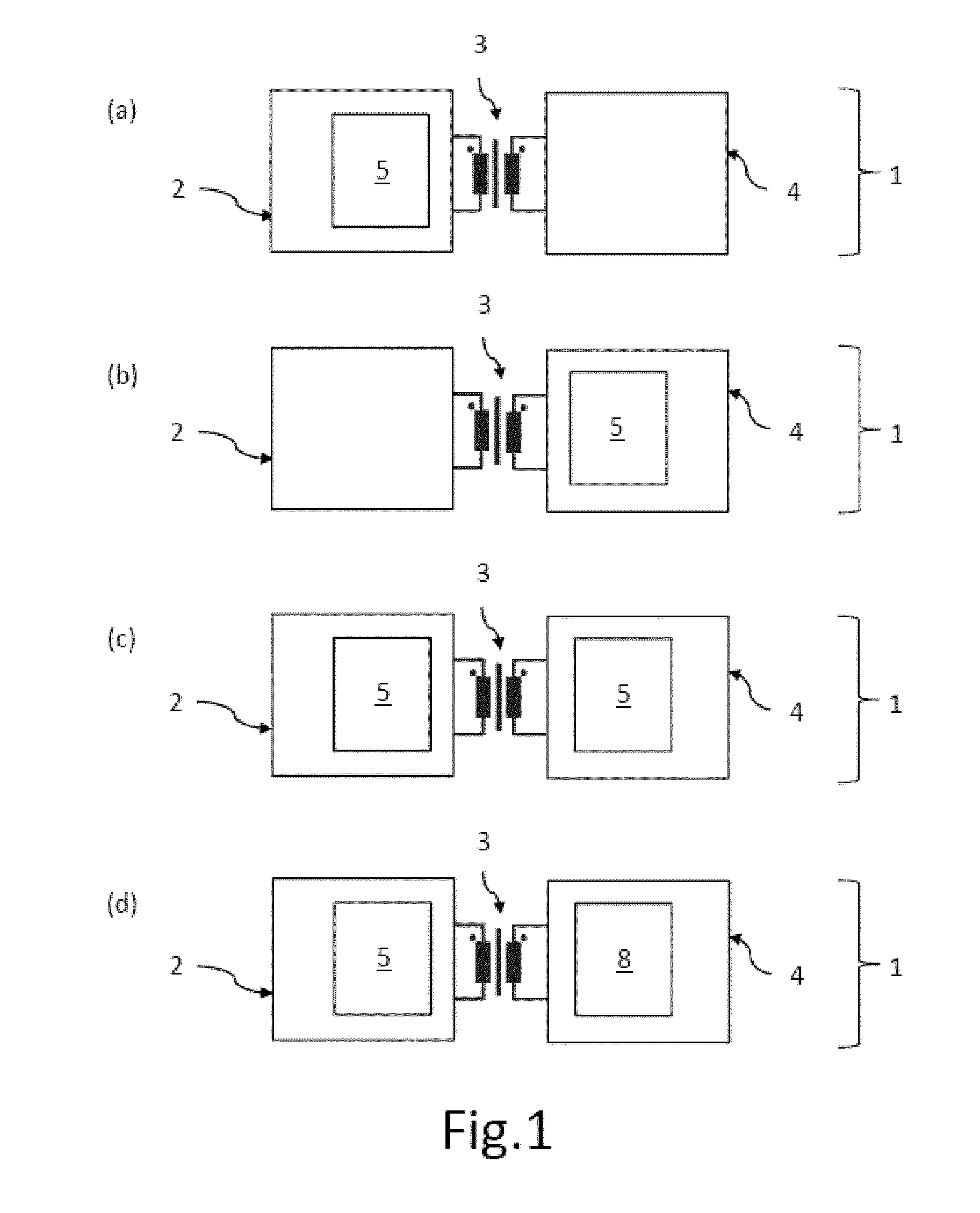
[0027]FIG. 1 shows several embodiments (a) to (d) of the bidirectional DC-DC converter 1, each having an input stage 2 to convert a DC input voltage into a first AC voltage, a transformer 3 to transform the first AC voltage into a second AC voltage, and an output stage 4 to convert the second AC voltage into a DC output voltage. The various embodiments (a) to (d) comprise at least one multi-level converter 5 in the input stage 2 and / or in the output stage 4. In embodiment (a), the multi-level converter 5 is situated in the input stage 2. In embodiment (b), the multi-level converter 5 is situated in the output stage 4. In embodiment (c), there is one multi-level converter 5 in the input stage 2 and one multi-level converter 5 in the output stage 4. In embodiment (d), the multi-level converter 5 is situated in the input stage 2, while the output stage 8 comprises a half-bridge or an H bridge.

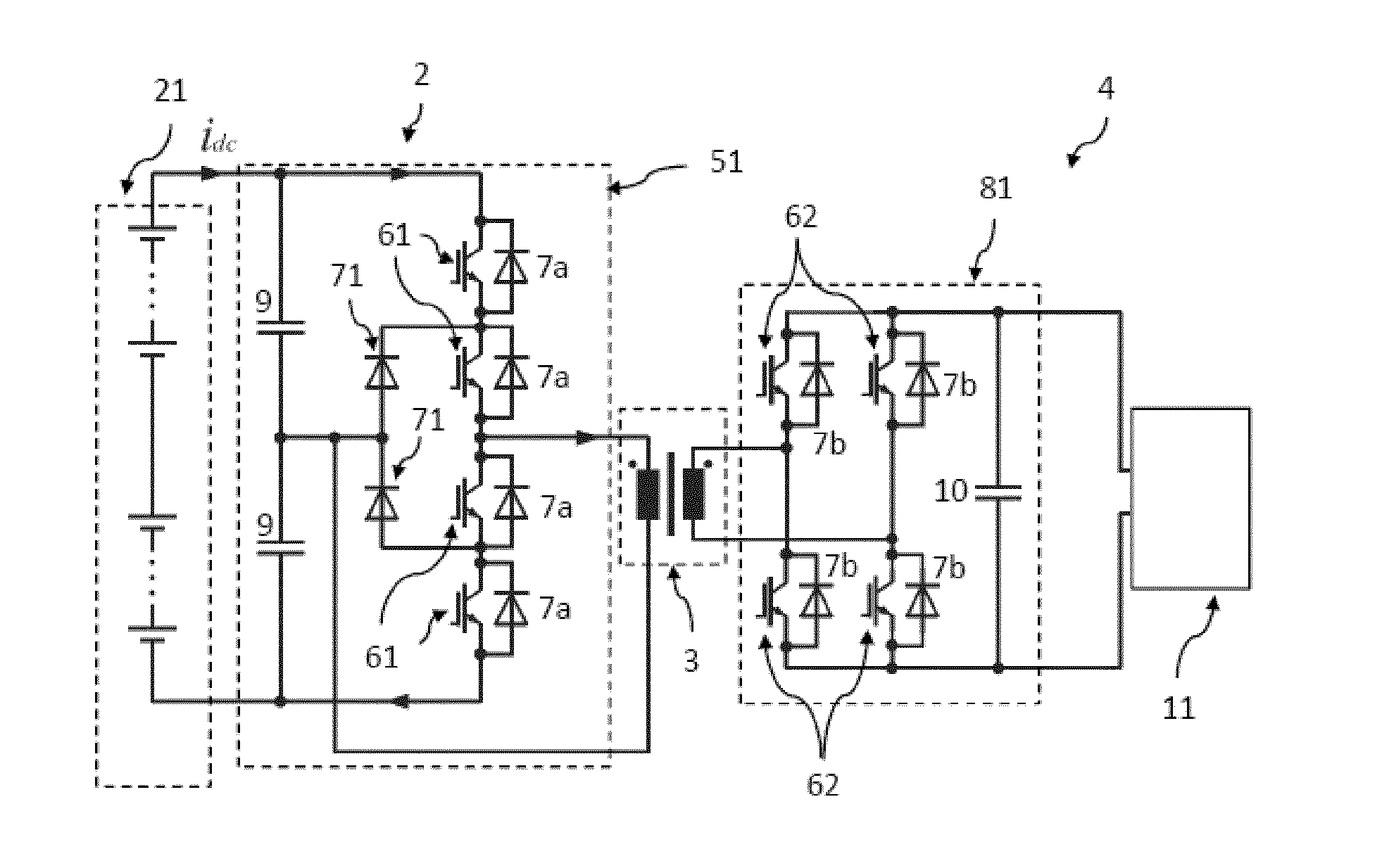
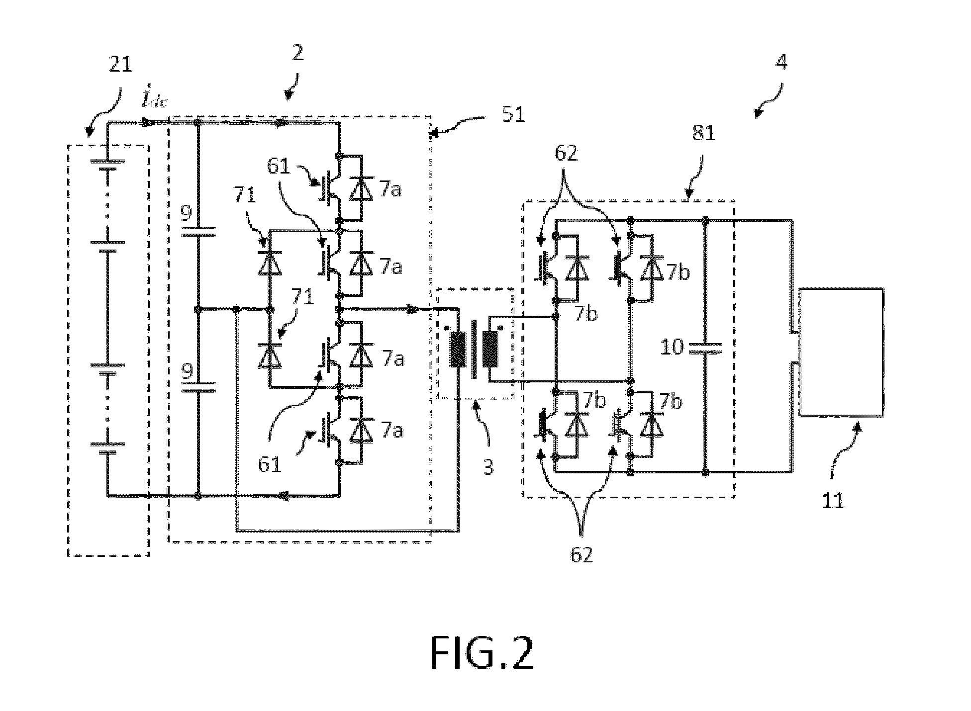
[0028]FIG. 2 shows a bidirectional DC-DC converter according to the present invention, with a ...


PUM


Abstract

The invention puts forward a bidirectional DC-DC converter for high voltages that is as simple as possible and that entails as few losses as possible. The bidirectional DC-DC converter (1) converter comprises an input stage (2) to convert a DC input voltage into first AC voltage, a transformer (3) to transform the first AC voltage into a second AC voltage, and an output stage (4) to convert the second AC voltage into a DC output voltage, whereby, in order to provide the first and/or second AC voltage, at least one of the input stages (2) and/or output stages (4) comprises a branch of a multi-level converter (5) with a first number of active first semiconductor switches (61).

Description

TECHNICAL FIELD OF THE INVENTION[0001]The invention relates to bidirectional DC-DC converters for high voltages.STATE OF THE ART[0002]A direct-current voltage converter, also known as a DC-DC converter, designates an electric circuit that converts a direct voltage fed in at the input into a direct voltage having a higher, lower or inverted voltage level. The conversion is performed employing a periodically operating electronic switch as well as one or more energy storage components. In the realm of electric energy technology, these converters are also referred to as DC chopper controllers.[0003]The inductor (inductive converter) used to temporarily store energy consists of a coil or of a converter-transformer. In contrast to this, converters with capacitive storage (capacitive converters) are referred to as charge pumps. Charge pumps are employed either when no inductors are present, as is the case in integrated circuits, or else when the power output needed is so low that it is not...

Claims


Application Information

Patent Timeline
IPC IPC(8): H02M3/335
CPCH02M3/33584H02M3/33571Y02E10/76
Inventor THOMAS, STEPHANDE DONCKER, IR RIK W.A.A.LENKE, ROBERT
Owner FLEXIBLE ELEKTRISCHE NETZE FEN GMBH
Why Eureka
Try Eureka