Crosstalk measuring method and crosstalk measuring device

a crosstalk measuring and measuring method technology, applied in transmission monitoring, transmission monitoring/testing/fault measurement systems, electrical equipment, etc., can solve problems such as inability to capture details, achieve more detailed crosstalk characteristics, reduce calculation load, and reduce storage capacity

Active Publication Date: 2014-01-02
THE FUJIKURA CABLE WORKS LTD +1
View PDF2 Cites 16 Cited by
  • Summary
  • Abstract
  • Description
  • Claims
  • Application Information

AI Technical Summary

Benefits of technology

[0029]When this crosstalk value calculating step or crosstalk value calculating unit is provided, it is possible to reduce storage capacity by a degree corresponding to reduction of model waveforms compared to a case when the waveform matching step or the waveform matching unit is provided. Further, it is possible to reduce a calculation load by a degree of skip of matching with model waveforms.
[0030]As described above, the present invention provides a crosstalk measuring method and a crosstalk measuring device which can capture more detailed crosstalk characteristics.

Problems solved by technology

However, according to the measuring method according to K. Takenaga et al., “Reduction of Crosstalk by Trench-Assisted Multi-Core Fiber” OFC2011, OWJ4, the entire multicore fiber is simplistically regarded as one channel, and therefore there is a problem that it is not possible to capture details such as a position of crosstalk in a core length direction and a level of the crosstalk.

Method used


Image

  • Crosstalk measuring method and crosstalk measuring device
  • Crosstalk measuring method and crosstalk measuring device
  • Crosstalk measuring method and crosstalk measuring device

Examples


first embodiment

(1) First Embodiment

[0050]FIG. 3 is a view illustrating a configuration of a crosstalk measuring device 1 according to the first embodiment. As illustrated in FIG. 2, the crosstalk measuring device 1 has an OTDR (Optical Time Domain Reflectometer) 2, a waveform processing unit 3 and a waveform matching unit 4 as main components.

[0051]2>

[0052]The OTDR 2 is a device which allows pulse light to enter an end of a measurement target optical fiber, and measures a distance distribution of an intensity of light reflected at each point in an optical fiber length direction and returning to an entrance end.

[0053]In case of the present embodiment, the OTDR 2 allows pulse light to enter one end E1 of, for example, the core 11 arranged in the center of the multicore fiber 10 or 20 through a measurement target optical fiber (referred to as a “dummy fiber” below) DF1 which allows pulse light to enter. Further, the OTDR 2 measures a distance distribution (referred to as a “first light intensity dist...

example 1

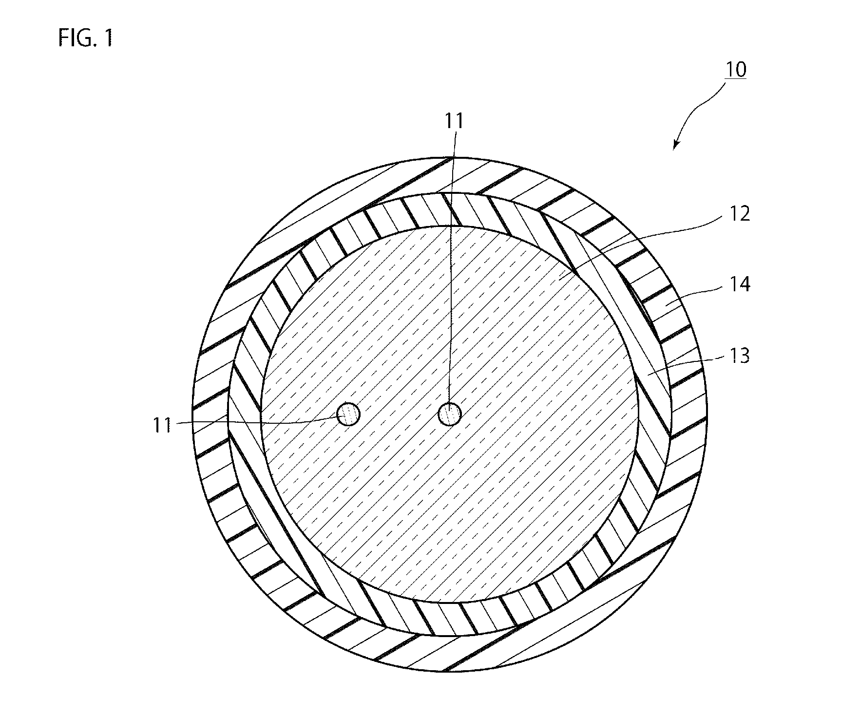
[0118]A two-core fiber as a sample of a multicore fiber 10 in which one core is arranged in the center, and one core is arranged at a position spaced 25 [μm] apart from this core is made to adopt a structure indicated in following Table 1.

TABLE 1Center coreOuter coreCore delta [%]0.80.8Core radius [μm]33Inter-core distance25[μm]Clad diameter [μm]160Fiber strip length [km]10

[0119]Further, two two-[km] single mode fibers are prepared as dummy fibers DF1 and DF2, and one end of one single mode fiber is fused to one end of the center core of the two-core fiber and one end of the other single mode fiber is fused to the other end of the center core of the two-core fiber.

[0120]FIGS. 8A and 8B illustrate added waveforms obtained when pulse light enters the center core of this two-core fiber through a single mode fiber and a first light intensity distribution and a second light intensity distribution are measured by an OTDR 2.

[0121]More specifically, FIG. 8A illustrates by a solid line an ad...

example 2

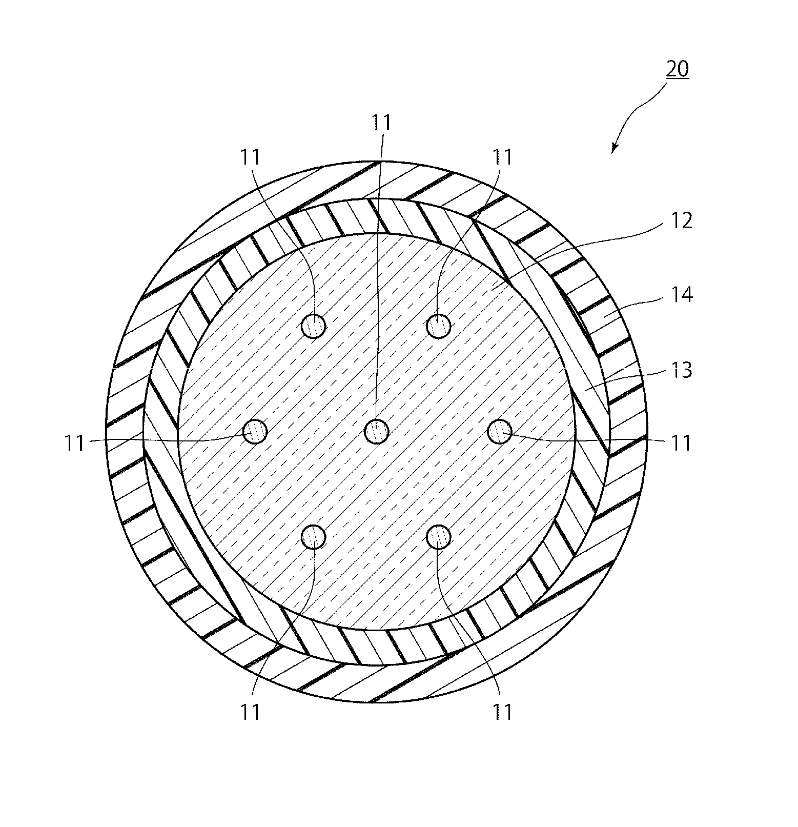
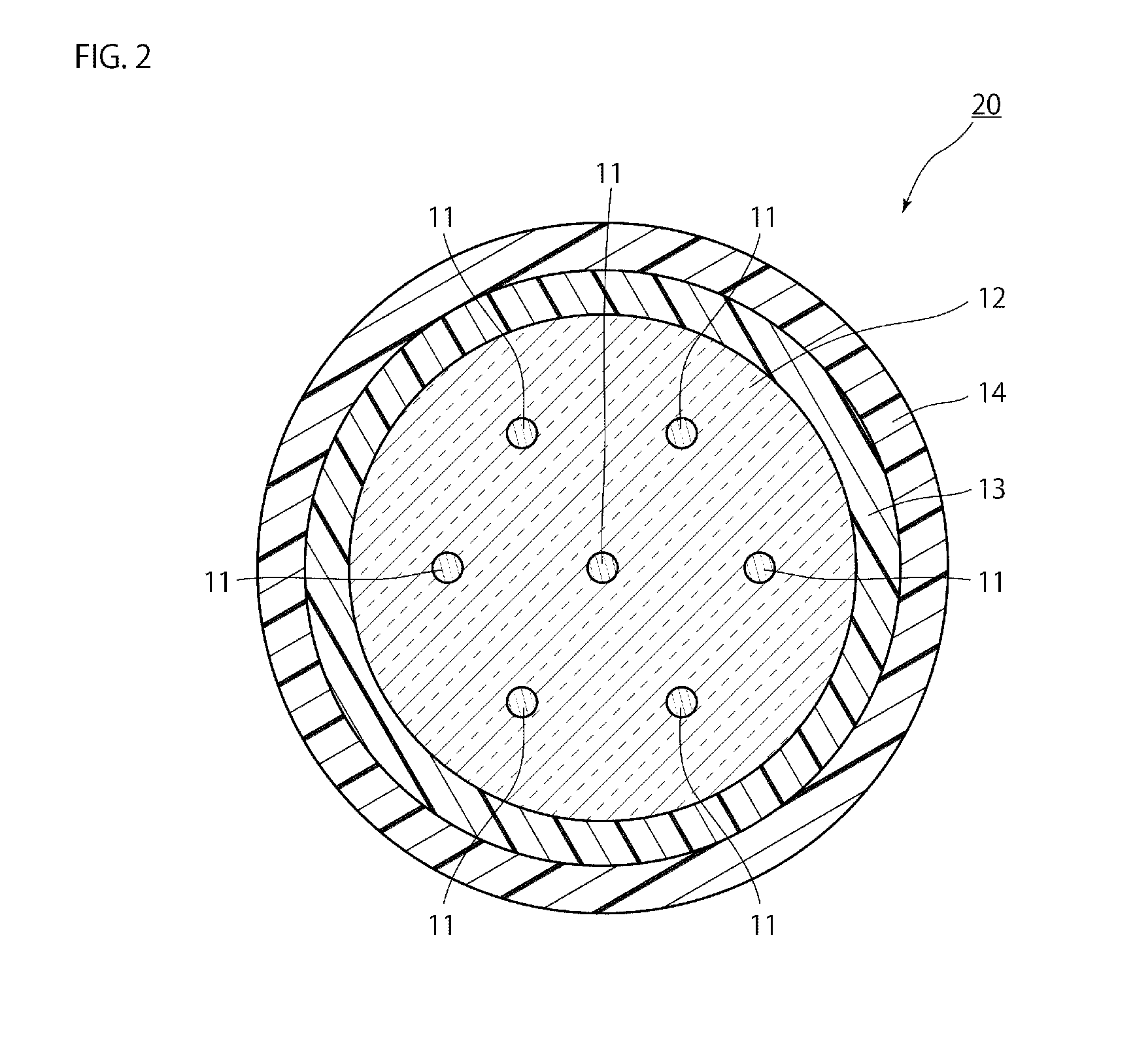
[0126]A seven-core fiber as a sample of a multicore fiber 20 in which one core is arranged in the center, and six cores are arranged at positions spaced 35 [μm] apart from this core is made to adopt a structure indicated in following Table 2.

TABLE 2Center coreOuter coreCore delta [%]0.350.35Core radius [μm]4.54.5Inter-core distance35[μm]Clad diameter [μm]195Fiber strip length [km]50

[0127]Further, two two-[km] single mode fibers are prepared as dummy fibers DF1 and DF2 similar to Example 1, and one end of one single mode fiber is fused to one end of the center core of the seven-core fiber and one end of the other single mode fiber is fused to the other end of the center core of the seven-core fiber.

[0128]FIGS. 10A and 10B illustrate added waveforms obtained when pulse light enters the center core of this seven-core fiber through a single mode fiber and a first light intensity distribution and a second light intensity distribution are measured by an OTDR 2.

[0129]More specifically, FIG...


PUM


Abstract

For example, of a first intensity distribution waveform WF1 indicated by a distance distribution of an intensity of light which returns to one end of a core of a multicore fiber, and a second intensity distribution waveform WF2 indicated by a distance distribution of an intensity of light which returns to the other end of the core, the second intensity distribution waveform WF2 is inverted. Further, for example, an inverted intensity distribution waveform WF3 which is inverted and the first intensity distribution waveform WF1 which is not inverted are added.

Description

BACKGROUND OF THE INVENTION[0001]The present invention relates to a crosstalk measuring method and a crosstalk measuring device, and is suitable to measure crosstalk in a multicore fiber.[0002]A multicore fiber has a structure which includes a plurality of cores and a clad which fills between the cores and surrounds all of the plurality of cores, and can transmit signals through respective cores.[0003]In this multicore fiber, crosstalk occurs between cores, and it is important to learn characteristics of this crosstalk.[0004]A measuring method of measuring a level of crosstalk is a measuring method disclosed in, for example, the following documents. According to this measuring method, a power ratio of light which enters one given core of the multicore fiber and light which is output from a core adjacent to the core is measured.[0005]K. Takenaga et al., “Reduction of Crosstalk by Trench-Assisted Multi-Core Fiber” OFC2011, OWJ4.SUMMARY OF THE INVENTION[0006]However, according to the m...

Claims


Application Information

Patent Timeline
Patent Type & Authority Applications(United States)
IPC IPC(8): H04B10/079
CPCH04B10/0795G02B6/02042H04B10/071
Inventor HAMAGUCHI, HIROKIMATSUO, SHOICHIROISHIDA, ITARUGOTO, YUKIHIRONAKAJIMA, KAZUHIDE
Owner THE FUJIKURA CABLE WORKS LTD
Why Eureka
Try Eureka