Repair Of A Shrouded Blade

a shroud and blade technology, applied in the field of shroud blade repair, can solve the problems of more extensive blade repair, affecting the dimensional relationship of the mating surface relative to the airfoil, and causing the blade to wear to varying degrees

Active Publication Date: 2014-01-02
ANSALDO ENERGIA SWITZERLAND AG
View PDF2 Cites 23 Cited by
  • Summary
  • Abstract
  • Description
  • Claims
  • Application Information

AI Technical Summary

Benefits of technology

[0007]In accordance with the present invention, there is provided a novel and improved method for repairing a blade having a shroud after gas turbine operation. The present invention is directed towards a way of measuring a set of previously-operated blades to determine their post-operation geometric characteristics and determining an offset of the hardface surfaces of the shroud portion of the blade due to engine-induced deformation. The hardface surfaces of the shroud are then machined to a first dimension and blade-compatible material is added to the hardface surfaces of the shroud. Next, a first side hardface surface of the shroud is machined to a desired offset dimension after which a second side hardface surface is machined such that the distance between the hardface surfaces satisfies the cross-shroud dimension similar to that of an originally manufactured blade. Such repair processes allows reuse of a turbine blade by accounting for movement of the shroud and wear on shroud hardfaces with minimal change of the as-designed dimensional relationship of the shroud surfaces relative to the airfoil.

Problems solved by technology

In operation, the shrouds of the blades are known to wear to varying degrees due to shroud-to-shroud rubbing and mechanical loading.
Prior repair techniques have attempted to repair shrouds to original manufactured dimensions and by doing so have not accounted for the deformation the blade has undergone during operation, thereby resulting in more extensive blade repairs and the potential to change the dimensional relationship of the mating surfaces relative to the airfoil.

Method used


Image

  • Repair Of A Shrouded Blade
  • Repair Of A Shrouded Blade
  • Repair Of A Shrouded Blade

Examples


Embodiment Construction

[0019]The subject matter of the present invention is described with specificity herein to meet statutory requirements. However, the description itself is not intended to limit the scope of this patent. Rather, the inventors have contemplated that the claimed subject matter might also be embodied in other ways, to include different components, combinations of components, steps, or combinations of steps similar to the ones described in this document, in conjunction with other present or future technologies.

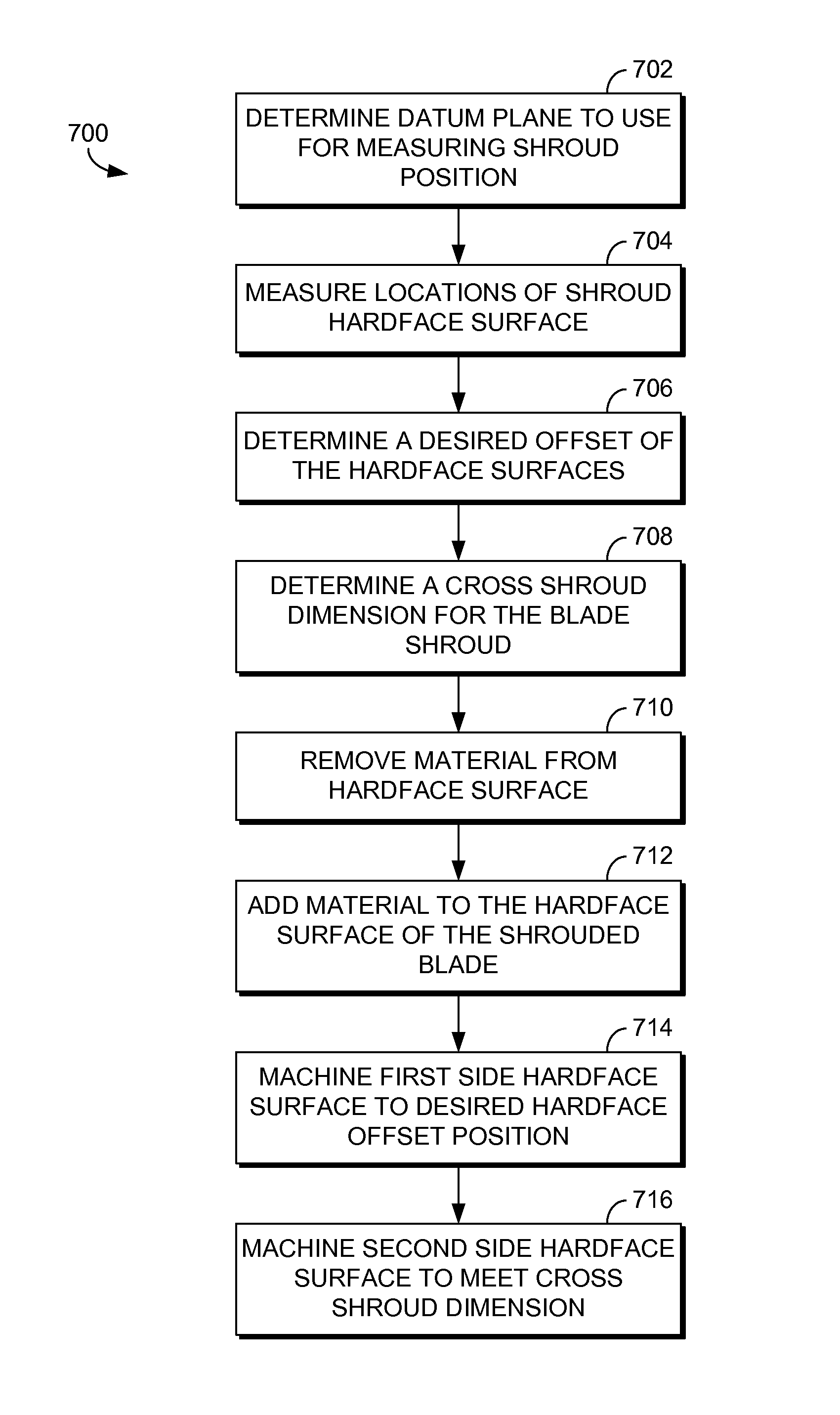
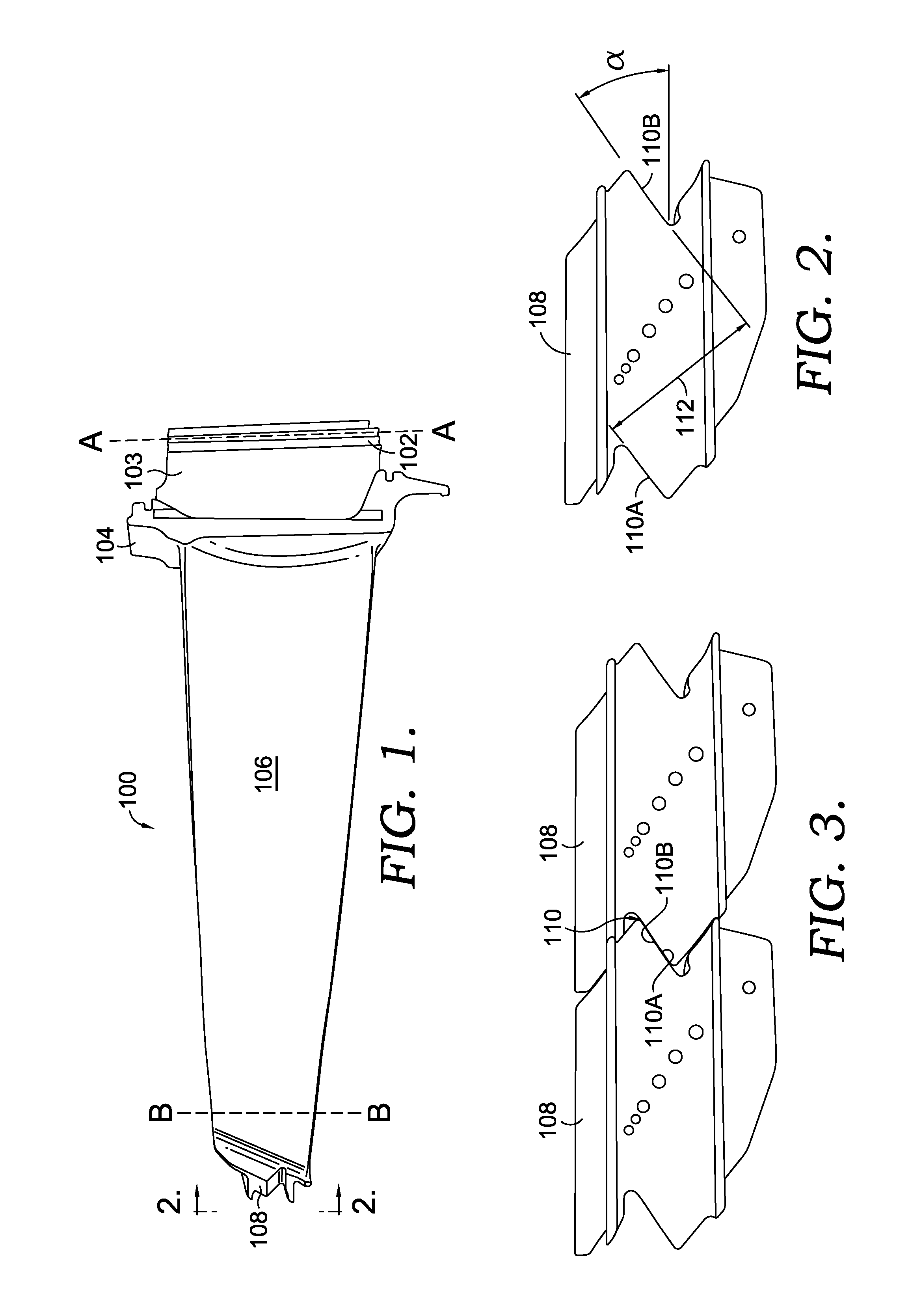
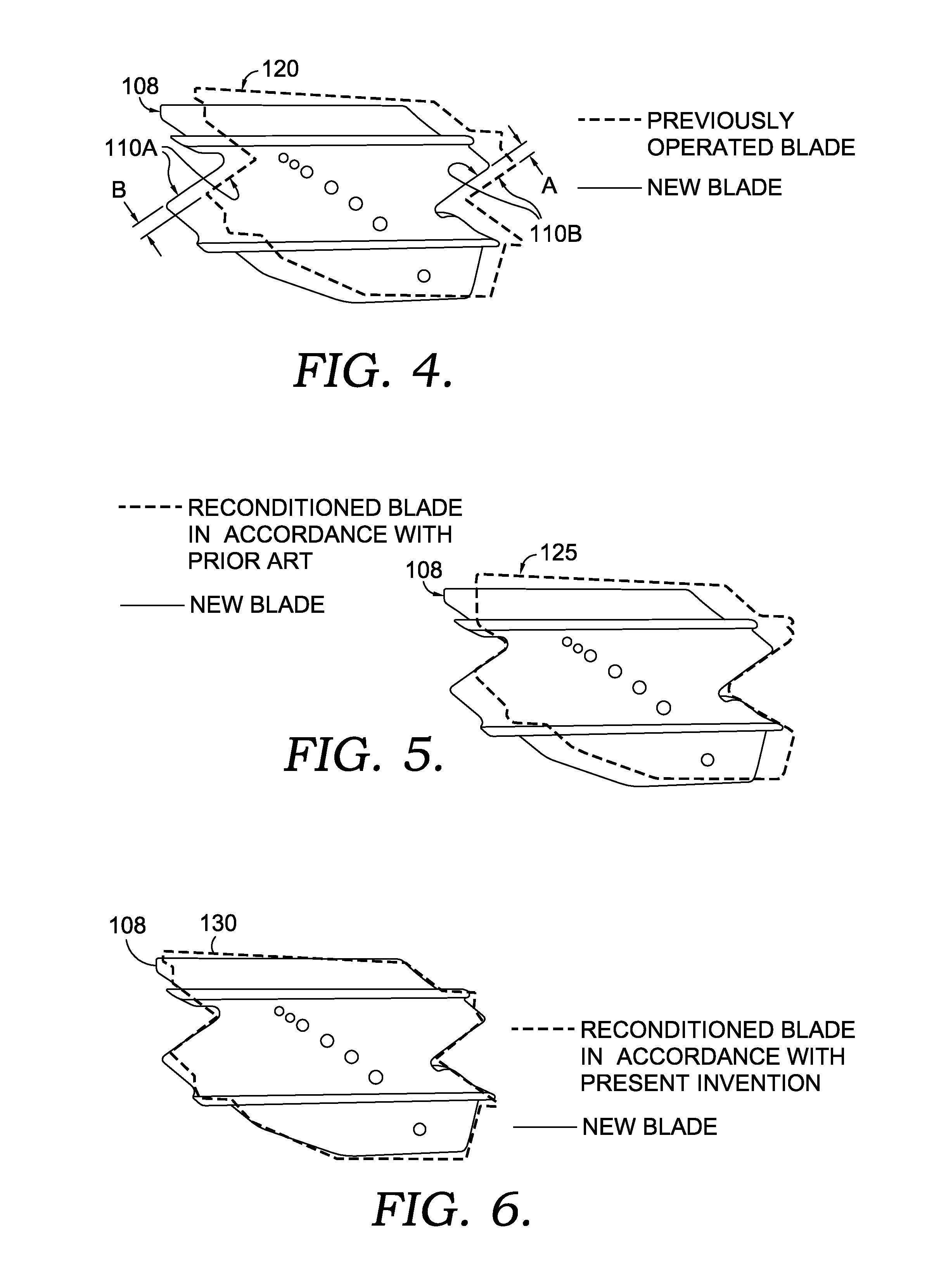
[0020]The present invention is shown in detail in FIGS. 1-7 and can be applied to a variety of shrouded blades exhibiting deflections or deformations caused by engine operation. The present invention provides a reconditioned blade and process by which the shroud of a blade which exhibits deflection and / or displacement usually caused by engine use can be refurbished while greatly maintaining the shroud-to-airfoil relationship of an originally-manufactured blade.

[0021]Referring initia...


PUM

PropertyMeasurementUnit
displacementsaaaaaaaaaa
displacementaaaaaaaaaa
dimensionaaaaaaaaaa

Abstract

The present invention discloses a novel and improved method for repairing a shrouded blade and a reconditioned shrouded blade. More specifically, a way of measuring a set of previously-operated blades to determine their post-operation geometric characteristics is provided where an offset due to deformation of the hardface surfaces of the shroud is determined. The hardface surfaces of the shroud are rough-machined and blade-compatible material is added to the hardface surfaces. A first side hardface surface of the shroud is then machined to a desired dimension offset relative to an originally manufactured blade after which a second side hardface surface is machined such that the distance between the hardface surfaces satisfies the cross-shroud dimension, which is similar to that of an originally manufactured blade.

Description

CROSS-REFERENCE TO RELATED APPLICATIONS[0001]This application claims priority to U.S. Provisional Patent Application Ser. No. 61 / 667,090 filed Jul. 2, 2012.TECHNICAL FIELD[0002]The present invention generally relates to a method of repairing a shrouded blade. More specifically, the present invention is directed towards a process by which a set of shrouded blades is refurbished by incorporating movement of the airfoil due to engine operation into the repairs made to a blade shroud.BACKGROUND OF THE INVENTION[0003]In a typical gas turbine engine, a compressor having alternating stages of rotating and stationary airfoils is coupled to a turbine, which also has alternating stages of rotating and stationary airfoils. The compressor stages decrease in size to compress the air passing therethrough. The compressed air is then supplied to one or more combustors which mixes the air with fuel and ignites the mixture. The expansion of the hot combustion gases drives the stages of a turbine, whi...

Claims


Application Information

Patent Timeline
Patent Type & Authority Applications(United States)
IPC IPC(8): F01D5/00
CPCF01D5/005B23P6/007Y10T29/49318
Inventor DUBS, GREGORY ALANMILIDANTRI, THOMAS HORACE
Owner ANSALDO ENERGIA SWITZERLAND AG
Why Eureka
Try Eureka