Aircraft main engine fuel pump with multiple gear stages using shared journals

a fuel pump and gear stage technology, applied in the direction of liquid fuel engines, machine/engines, rotary/oscillating piston pump components, etc., can solve the problems of premature wear of journal bearings, gear tooth failure, and first pump inclination to become unstable, so as to reduce the possibility of bearing oil whirl, limit premature wear, and minimize energy consumption

Active Publication Date: 2014-01-02
EATON INTELLIGENT POWER LIMITED
View PDF2 Cites 20 Cited by
  • Summary
  • Abstract
  • Description
  • Claims
  • Application Information

AI Technical Summary

Benefits of technology

[0015]The shared journal arrangement limits premature wear since the journals are always loaded and provide the needed pre-load to reduce the prospect of bearing oil whirl during periods when the first pump is unloaded, and when the discharge pressure is rapidly turned on or off.
[0016]Energy consumption is minimized during flight since one or more of the multistage gear stages can be operated at a reduced pressure loading.
[0017]By locating the gear and stages on the same journal shaft, the load can be transferred through the shaft and not through the teeth, reducing the tooth load and therefore their size.
[0018]Reduced or limited tooth bounce results from the improved stability.

Problems solved by technology

Inclusion of independent gear pumps in the same housing raises a number of issues.
In the reduced pressure state, the first pump has a tendency to become unstable.
As a result of the teeth of the gears transferring the relatively low load, there is resultant tooth bounce and instability, which could ultimately lead to gear tooth failure.
This gear instability can prematurely wear the journal bearing.
The bearings that support the arrangement can also become unstable when minimizing pressure to the first pump.
A phenomenon known in the industry as bearing oil whirl can occur in journal bearings that are lightly loaded, which could ultimately lead to bearing failure.
This results in increased loading on the gear teeth of the first pump, which would require an increase in the gear teeth size or count and increasing weight for example.
There are also issues with selectively switching between single and multistage use of the pump.
Thus, a conventional arrangement where the first and second gear pumps are offset from one another may address a portion of the issues associated with one pump being independent of the other, but it unnecessarily adds additional components, additional wear, additional weight, and increases the overall size of the multistage pump assembly.

Method used


Image

  • Aircraft main engine fuel pump with multiple gear stages using shared journals
  • Aircraft main engine fuel pump with multiple gear stages using shared journals
  • Aircraft main engine fuel pump with multiple gear stages using shared journals

Examples


Embodiment Construction

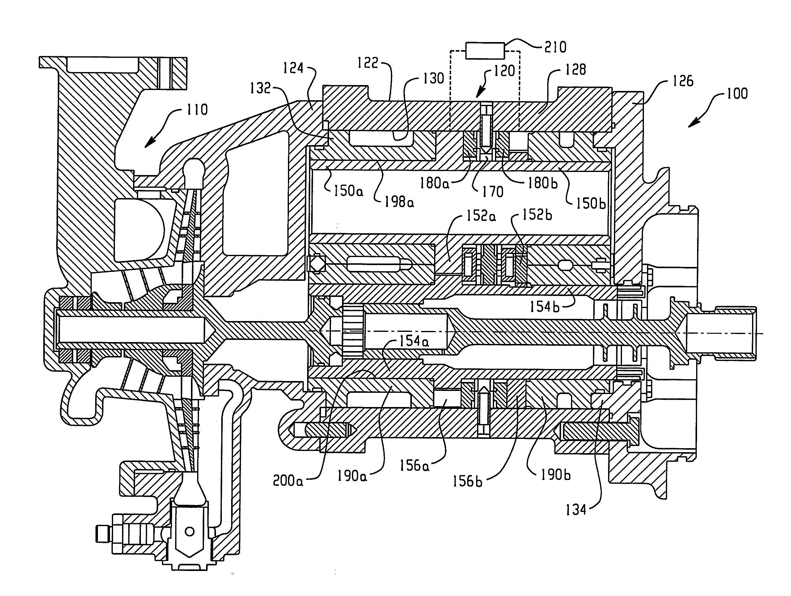
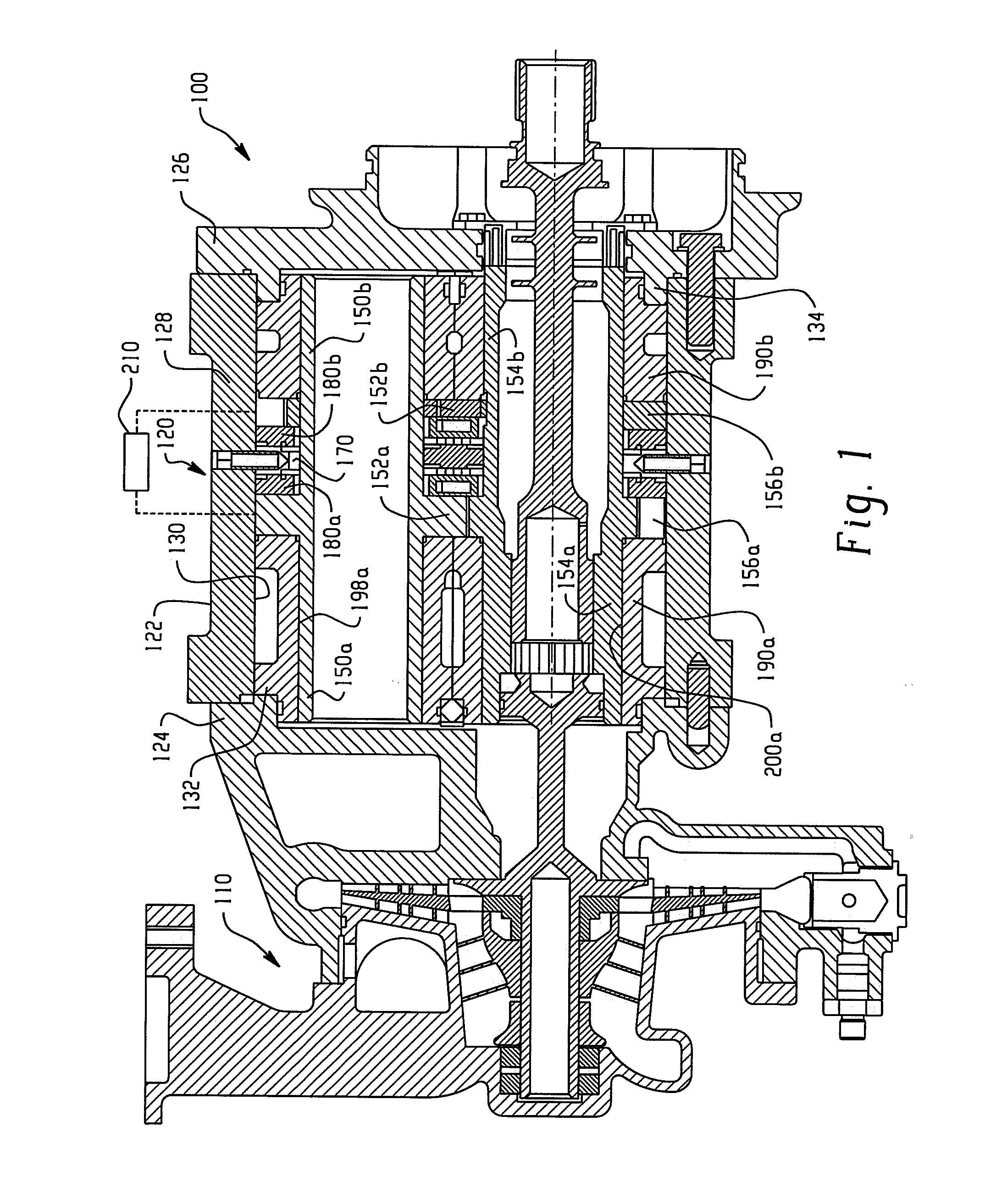
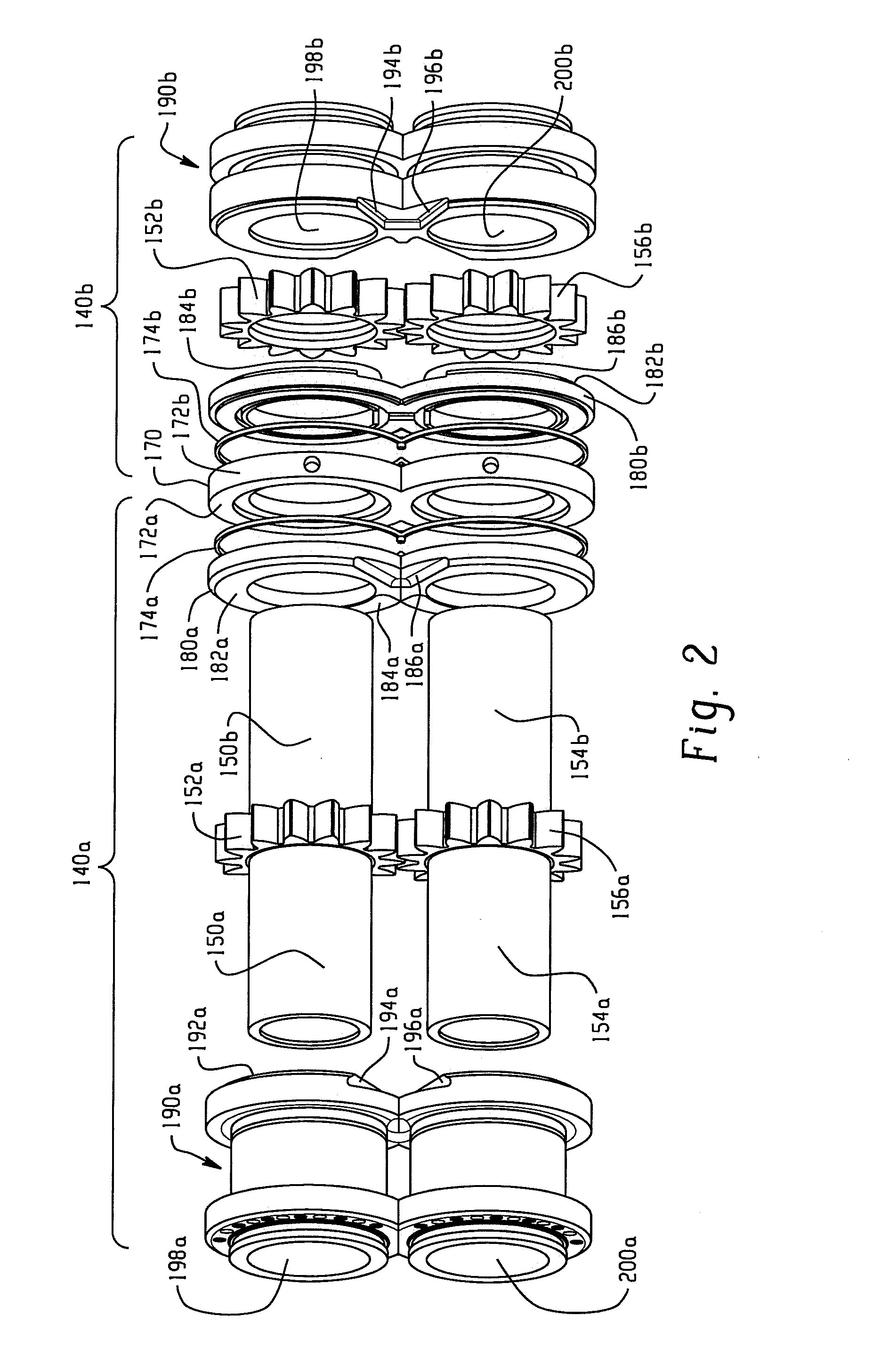
[0024]Portions of a fuel supply system 100 are shown in FIG. 1 and include a low pressure centrifugal pump 110 and a multistage positive displacement pump assembly or gear pump assembly 120. In FIG. 1, the multistage pump assembly 120 includes a housing 122 having a first end portion 124, and a second end portion 126 interconnected by a central sleeve 128. The sleeve 128 is secured at opposite ends to the first and second housing end portions 124, 126, respectively. For example, fasteners secure the end portions to the ends of the sleeve. In addition, the sleeve portion 128 of the housing includes an opening such as a constant diameter bore 130 extending through the housing. In this manner, the housing portion 124 forms a first shoulder at a first end 132 and the second housing portion 126 forms a second shoulder 134 at the opposite end. Between these shoulders and along the extent of the throughbore 130 are received first and second gear pumps 140a, 140b. For purposes of brevity an...


PUM


Abstract

A multistage gear pump assembly includes first and second gear pumps that use common shafts and are axially separated by a fixed spacer within the housing. Pressurized bearings are provided at opposite axial ends of the first and second gear pumps. The second gear pump handles cruise and idle operations of the aircraft while the first gear pump stage assists in meeting higher demand modes of engine operation. Otherwise, the first gear pump is maintained at a minimal pressure to reduce energy consumption and still provide desired stability and eliminate issues associated with bearing oil whirl associated with prior known arrangements. When additional assistance is required, such as during takeoff, climb, or windmill relight, the first gear pump advantageously contributes to the increased pressure.

Description

BACKGROUND OF THE INVENTION[0001]This application is a continuation-in-part and claims the priority benefit of U.S. application Ser. No. 12 / 424,745, filed Apr. 16, 2009, the disclosure of which is incorporated herein by reference.[0002]This disclosure relates to a multi-stage pump, and particularly to a multi-stage gear pump assembly used as a fuel pump in an aircraft gas turbine engine. It will be appreciated however, that the disclosure may find application in related environments and applications that encounter the same issues.[0003]A large portion of aircraft engine operation involves cruise and idle situations which do not demand large quantities of fuel flow. However, certain circumstances require additional flow, for example during takeoff, climb, or windmill re-light. The fuel pump assembly must be able to satisfy both demands, while adequately addressing associated parameters such as fuel pump size, efficiency, etc. For example, it is known to employ multiple stages of a po...

Claims


Application Information

Patent Timeline
Patent Type & Authority Applications(United States)
IPC IPC(8): F04C11/00
CPCF04C11/001F04C2/086F04C2/14F04C2/18F04C15/0023F04C15/0026F04C2210/1044F04C2240/52F04C2240/56
Inventor MARTIN-DYE, SIMON
Owner EATON INTELLIGENT POWER LIMITED
Why Eureka
Try Eureka