System and Method for Controlling Machines According to Pattern of Contours

a technology of contour pattern and machine, applied in the direction of electric programme control, program control, instruments, etc., to achieve the effect of optimizing the speed of machining

Active Publication Date: 2014-01-02
MITSUBISHI ELECTRIC RES LAB INC
View PDF8 Cites 49 Cited by
  • Summary
  • Abstract
  • Description
  • Claims
  • Application Information

AI Technical Summary

Benefits of technology

[0010]Some embodiments are based on a realization that to optimize the speed of the machining, a tool-head of a machine should proceed to enter and exit points of each segment contour on a tangent, while optimally matching the maximum cutting speed for that segment based on its curvature and dynamics of t...

Problems solved by technology

A further complication is that some cutters may have “no-fl...

Method used


Image

  • System and Method for Controlling Machines According to Pattern of Contours
  • System and Method for Controlling Machines According to Pattern of Contours
  • System and Method for Controlling Machines According to Pattern of Contours

Examples


Embodiment Construction

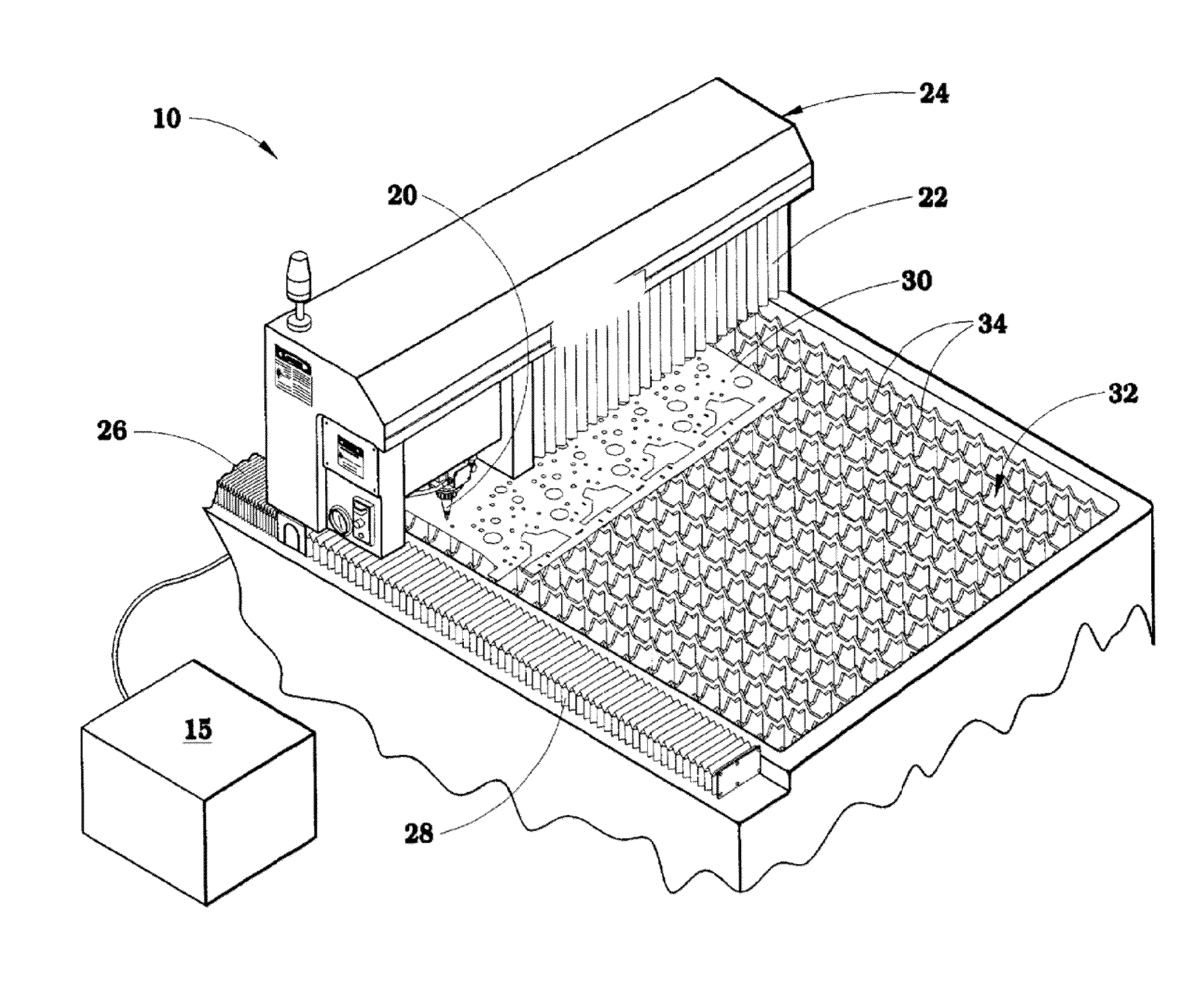
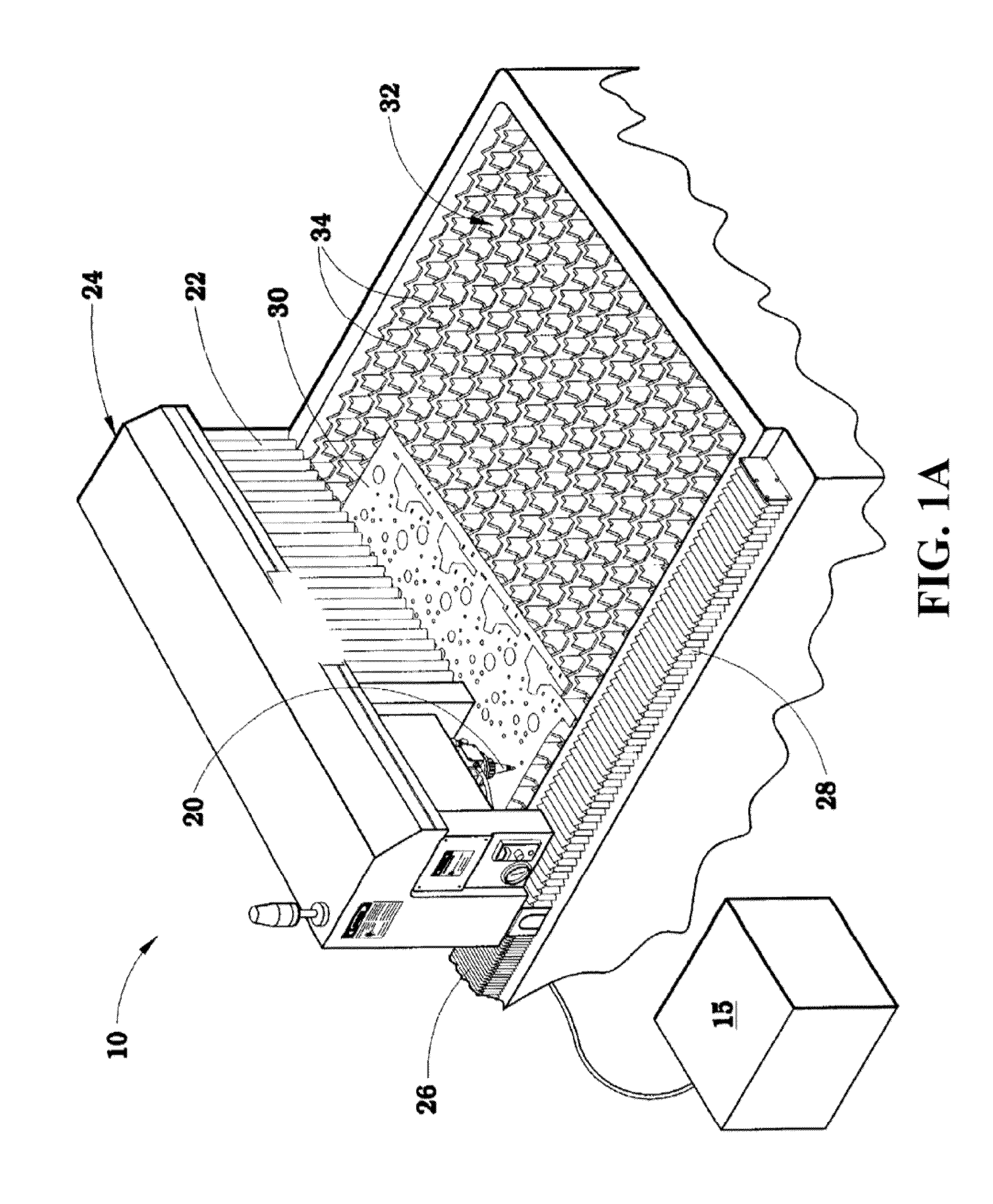
[0025]FIG. 1A shows an example of a laser cutting machine 10 suitable for being controlled by some embodiments of the invention. For simplicity of explanation and without loss of the generality, the machining is exemplified as a process of cutting the work-piece using a laser cutting machine.

[0026]The machine 10 is configured for moving the laser head 20 in any direction parallel to the surface of a piece of sheet material that is to be cut into specific shapes. The laser head 20 is a non-contact device which typically maintains a distance when in its “down” position from the tip of the laser head to the top surface of the sheet material being cut. Other types of laser heads, including “contact”-type heads are also possible.

[0027]The laser head 20 is mounted on a carriage so as to be able to move back and forth in a linear direction perpendicular to the longitudinal dimension of the main table of the laser cutting machine. As the laser head 20 traverses in this perpendicular directi...


PUM


Abstract

A set of costs representing operations of a machine along a set of trajectories connecting a set of exit and entry points on contours of a pattern is determined. Each trajectory represents an operation of the machine proceeding from an exit point with an exit velocity to an entry point with an entry velocity according to dynamics of the machine. The set of trajectories includes at least one trajectory representing the operation along a contour with non-zero velocities at corresponding exit and entry points, and at least one trajectory representing the operation between different contours with non-zero velocities at the corresponding exit and entry points. A sequence of the trajectories optimizing a total cost of operation of the machine tracking the pattern is determined based on the costs, and a set of instructions for controlling the machine is determined according to the sequence.

Description

FIELD OF THE INVENTION[0001]This invention relates generally to a system and a method for generating motion plans for machines, and more particularly to determining a set of instructions for controlling the machines according to a pattern of contours.BACKGROUND OF THE INVENTION[0002]In computer numerically controlled (CNC) machining, a tool-head is moved relatively to a-work-piece according to a predetermined pattern to perform machining of the work-piece. The machining can include various types of processing of the work-piece, such as cutting or drilling the work-piece. For simplicity of explanation and without loss of the generality, in this disclosure the machining is exemplified as a process of cutting the work-piece using a laser cutting machine.[0003]Cutting features from sheet material according to a pattern is a common manufacturing process. Generally, a cutting head of a laser cutting machine is translated in a bounded plane along orthogonal axes. Laser cutters of this type...

Claims


Application Information

Patent Timeline
IPC IPC(8): G05B19/18
CPCG05B19/31G05B19/4103G05B2219/34112G05B2219/36199G05B2219/45041G05B2219/49372
Inventor BRAND, MATTHEW
Owner MITSUBISHI ELECTRIC RES LAB INC
Why Eureka
Try Eureka