Concealing access patterns to electronic data storage for privacy

a technology of electronic data storage and access patterns, applied in the field of computer security, can solve the problems of malicious attackers and others obtaining sensitive information, and achieve the effects of preventing malicious attackers, enabling file encryption, and facilitating access patterns

Inactive Publication Date: 2014-01-02
RGT UNIV OF CALIFORNIA
View PDF6 Cites 56 Cited by
  • Summary
  • Abstract
  • Description
  • Claims
  • Application Information

AI Technical Summary

Benefits of technology

[0012]A method of concealing access patterns to data storage systems, including disk and / or memory, such as in a cloud environment, to protect privacy. The inventive method augments the use of file encryption, preventing malicious attackers, and even the cloud provider itself from being able to determine which files (or portions of files) the client is accessing. Without this form of security, malicious attackers and others could obtain sensitive information about what operations clients are performing with their sensitive data at different points in time.

Problems solved by technology

Without this form of security, malicious attackers and others could obtain sensitive information about what operations clients are performing with their sensitive data at different points in time.

Method used


Image

  • Concealing access patterns to electronic data storage for privacy
  • Concealing access patterns to electronic data storage for privacy
  • Concealing access patterns to electronic data storage for privacy

Examples


embodiment 30

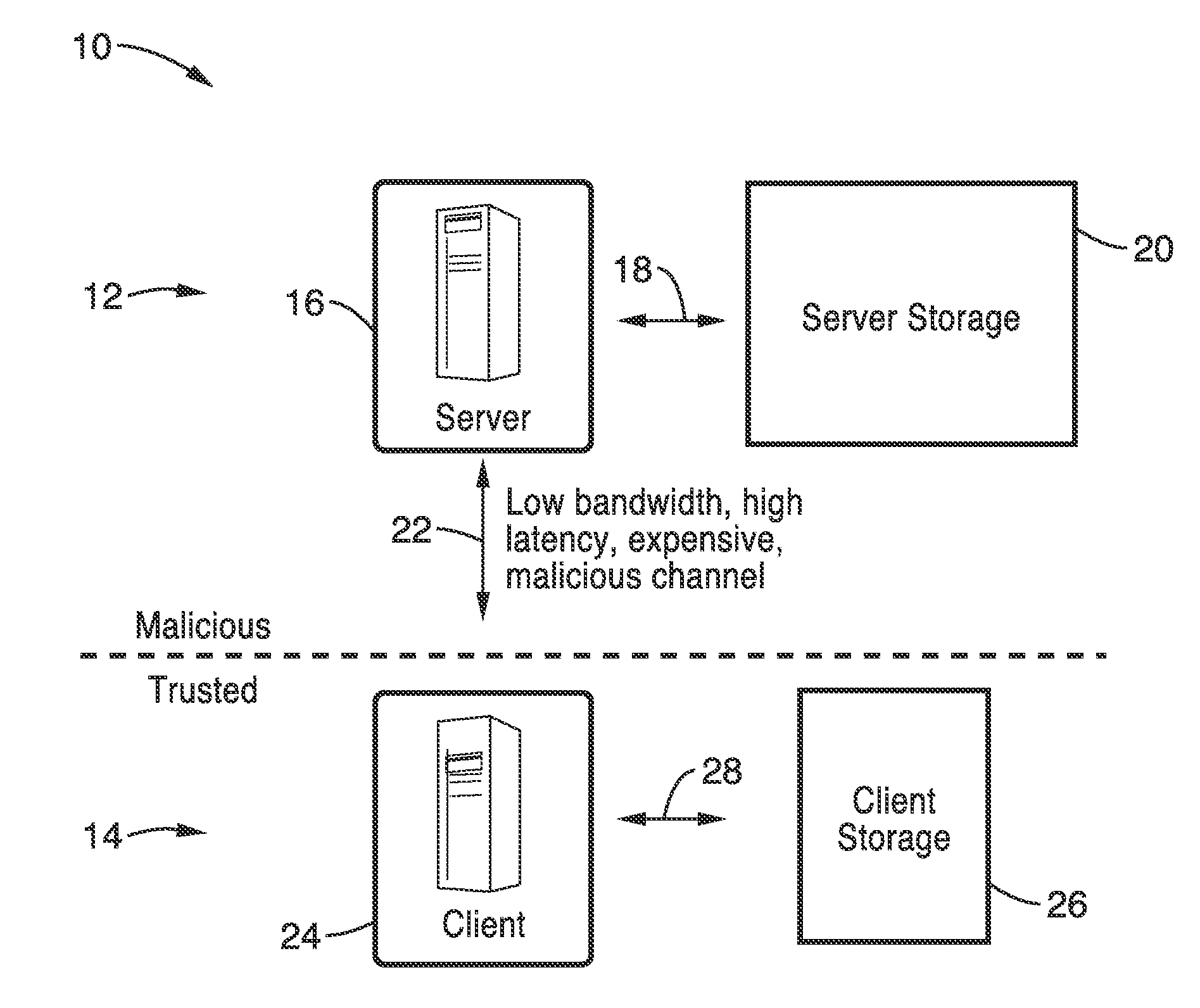
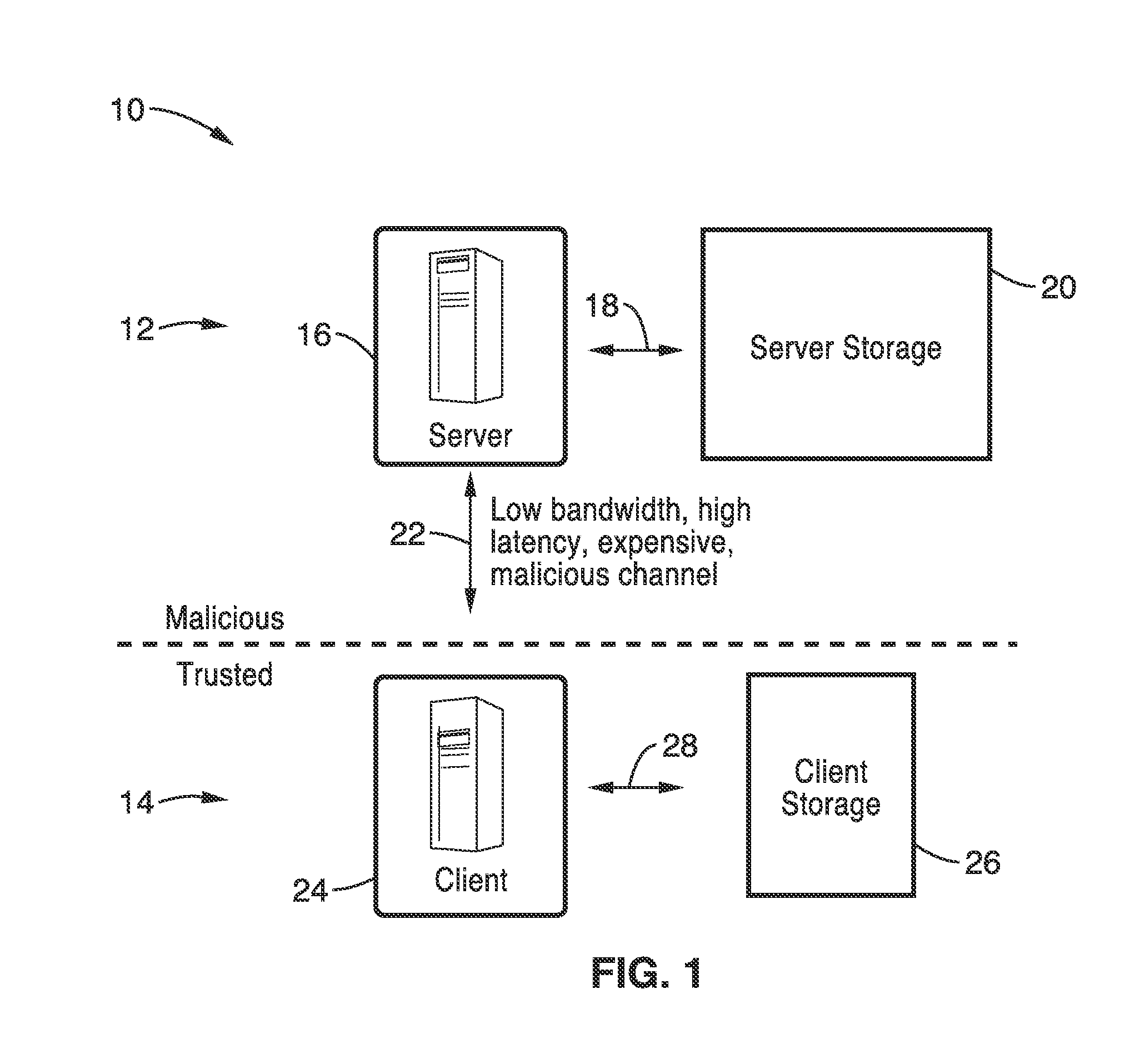
[0072]FIG. 2 illustrates an example of a partitioning framework embodiment 30 for the inventive O-RAM system. A server 32 and client side 34 are seen in the figure, as were seen in FIG. 1. On server side 32 partitions 40a through 40e are shown in server storage 20 dividing up the memory that the server uses (e.g., server providing cloud storage services) in fulfilling client requests for storing data. It should be appreciated that in this figure, as well others herein, the number of partitions, slots, blocks, positions in the shuffling buffer and position map are shown by way of simple illustration, however, the practice of the invention is not limited by the number of elements shown by illustration. On client side 34 the figure show a shuffling buffer 36, a position map 38, and a series of cache slots 42a through 42e contained within client storage 26, which was shown in FIG. 1. It will be seen in the figure that cache slots 42a through 42e correspond to partitions 40a through 40e ...

embodiment 190

[0233]FIG. 13 illustrates an example recursive construction embodiment 190. The server side 192 is exemplified with a plurality of O-RAMs (partition groups) 198, 200 and 202 each having inner O-RAMs as partitions. On the client side 194 cache slots are seen associated with each of these O-RAMs within groups 204, 206 and 208. The client side 194 also shows a shared shuffling buffer 196. As seen in the figure, the position map for O-RAM 198 is stored on O-RAM 200, while client position map for O-RAM 200 is stored on O-RAM 202, and so forth. Accordingly, each of the partition groups is just an instance of the O-RAM process of the invention. One should appreciate that the position map of an O-RAM is replaced with another O-RAM and so forth (recursion), while the remainder of the O-RAM method processing remains the same. Captions below each O-RAM indicate the number of partitions the O-RAM has and how many blocks are in each of those partitions.

[0234]Intuition. Instead of storing the lin...

embodiment 210

[0286]FIG. 14 and FIG. 15 illustrate two general O-RAM deployment embodiments. In FIG. 14 a hybrid cloud embodiment 210 of O-RAM deployment is shown. In FIG. 15 there is some trusted hardware in the cloud. This approach appears one promising topology for building future privacy-preserving cloud services. It should be appreciated that FIGS. 14 and 15 are provided by way of example for deploying the inventive O-RAM methods and apparatus, although the inventive elements can be integrated within a wide range of known and proposed topologies, and combinations thereof, without departing from the teachings of the present invention.

[0287]11.1 Hybrid Cloud.

[0288]Referring again to embodiment 210 of FIG. 14 there is an untrusted cloud 212 which is being utilized by a private cloud 214. Within the private cloud are a plurality of clients 216, each client comprising a computer system with secure storage needs. These clients 216 are connected into an oblivious load balancer 218 which directs ope...


PUM


Abstract

Methods and systems of concealing access patterns to data storage, such as within servers of a cloud computing environment are presented. Server data storage is securely partitioned into smaller electronic data storage partitions of predetermined size. The client side maintains a shuffling buffer and position map for these blocks as stored on the electronic data storage partitions of the server. Concealment is performed with respect to accesses from the client to server using an oblivious sorting protocol. Access operation is concealed with each block being randomly assigned to any of the data storage partitions, and whenever a block is accessed, the block is logically removed from its current partition and logically assigned to a fresh random partition selected from all partitions, while the client maintains tracking of which partition each block is associated with at any point of time.

Description

CROSS-REFERENCE TO RELATED APPLICATIONS[0001]This application is a nonprovisional of U.S. provisional patent application Ser. No. 61 / 660,654 filed on Jun. 15, 2012, incorporated herein by reference in its entirety.STATEMENT REGARDING FEDERALLY SPONSORED RESEARCH OR DEVELOPMENT[0002]This invention was made with Government support under Grant No. DGE-0946797 awarded by the National Science Foundation, under Grant Numbers CCF-0424422, 0311808, 0832943, 0448452, 0842694, 0627511, 0842695, 0808617, and 0831501 CT-L awarded by the National Science Foundation, under Grant No. FA9550-09-1-0539 awarded by the Air Force Office of Scientific Research, under Grant No. P010071555 awarded by the Air Force Research Laboratory, under Grant No. N000140911081 awarded by the Office of Naval Research, and under Grant No. FA9550-08-1-0352 awarded by the Air Force Office of Scientific Research. The Government has certain rights in this invention.INCORPORATION-BY-REFERENCE OF MATERIAL SUBMITTED ON A COMPA...

Claims


Application Information

Patent Timeline
Patent Type & Authority Applications(United States)
IPC IPC(8): G06F21/60
CPCG06F21/60G06F21/606G06F21/6254G06F2221/2123
Inventor STEFANOV, EMILSHI, ELAINESONG, DAWN
Owner RGT UNIV OF CALIFORNIA
Why Eureka
Try Eureka