
Helical spline forming

a helical spline and forming technology, applied in the field of forming parts, can solve the problems of complex process, high cost and time consumption, and poor design of process and design, and achieve the effects of reducing damage and backlash of engaging components, cost effective and efficient, and reducing stress concentration

Active Publication Date: 2014-01-09
MAGNA POWERTRIAN INC (US)
View PDF4 Cites 3 Cited by
  • Summary
  • Abstract
  • Description
  • Claims
  • Application Information

AI Technical Summary

Benefits of technology

This patent is about a new process for making a final part with helical splines that have advantages such as reducing stress concentrations and minimizing damage and backlash of engaging components. The process is cost-effective and efficient, as it requires fewer steps and uses a one-piece design. The technique can work with many different part designs and materials, including relatively lower carbon metals and higher carbon steels. The technique has been tested and proven successful for final part ejection from the flow forming tool while still maintaining dimensional accuracy and integrity of the helical splines of the final part.

Problems solved by technology

However, such a process and design has been found to work very poorly when the mandrel is designed to form a axially-offset spline, such as a helical spline, on the pre-form.
Such attempts to remove a final part including helical splines have not met with success.
Such alternatives including processes using traditional broaching and hobbing methods which are multistep, expensive and time consuming processes.
But the current use of these generally known techniques or systems for final parts having helical splines significantly increases the final and overall costs and inefficiency in creating such a final product.
In addition, despite many varied attempts, the flow forming process fails to protect the integrity of the final part and in particular, the dimensional integrity of the helical splines.
The traditional broaching and hobbing techniques remain in use but are costly and inefficient.

Method used


Image

  • Helical spline forming
  • Helical spline forming
  • Helical spline forming

Examples


Embodiment Construction

[0022]The following description of the preferred embodiment(s) is merely exemplary in nature and is in no way intended to limit the invention, its application, or uses.

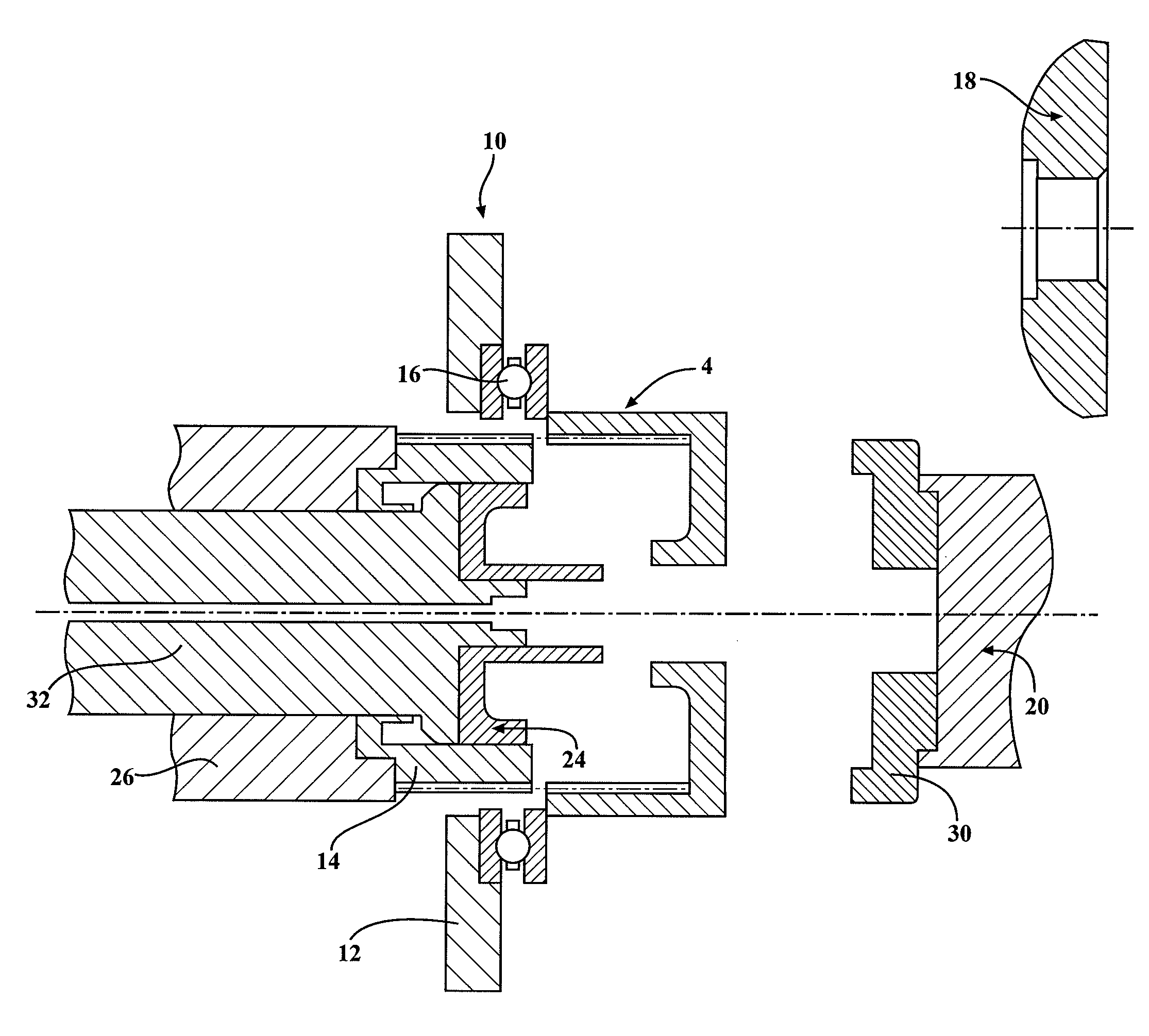
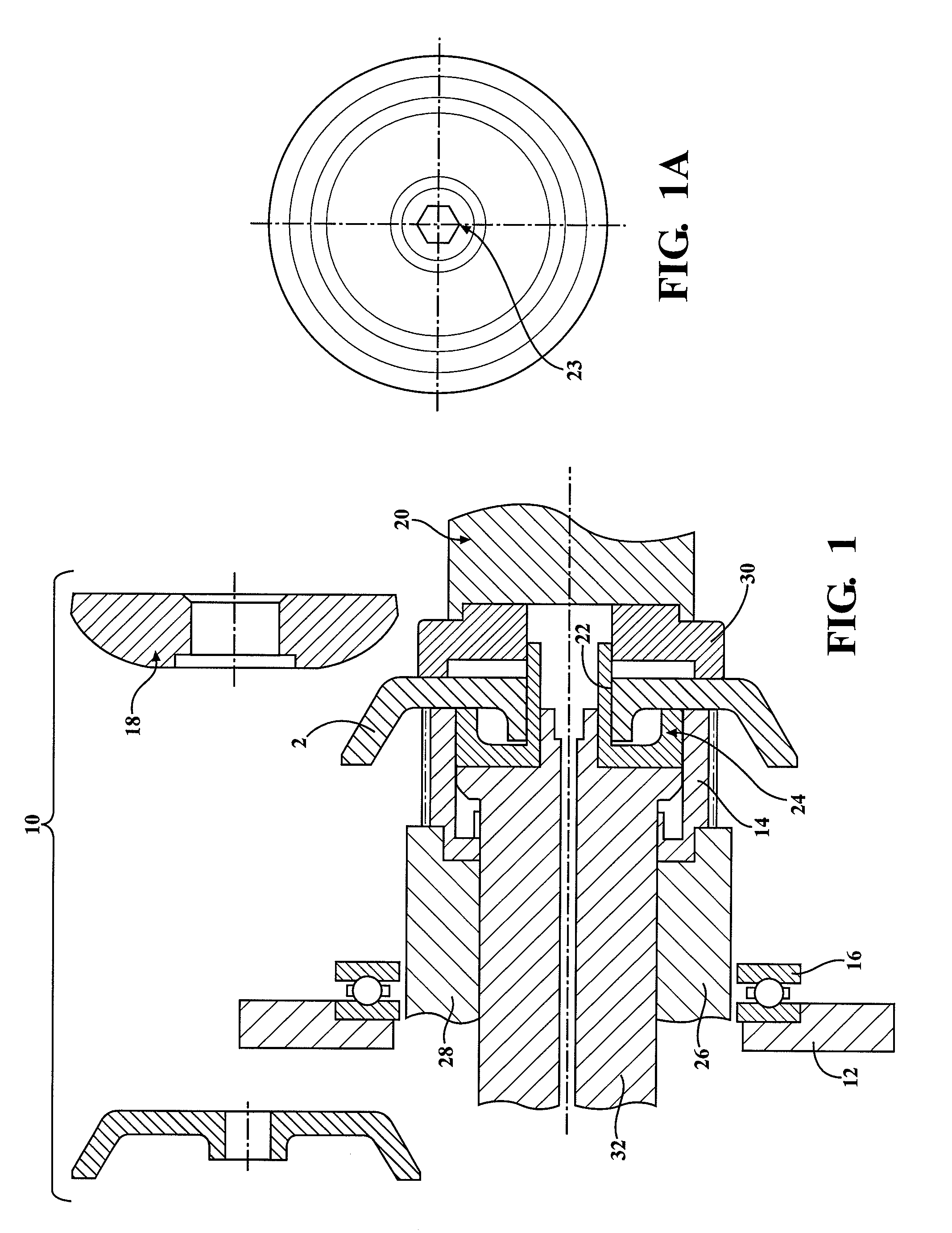
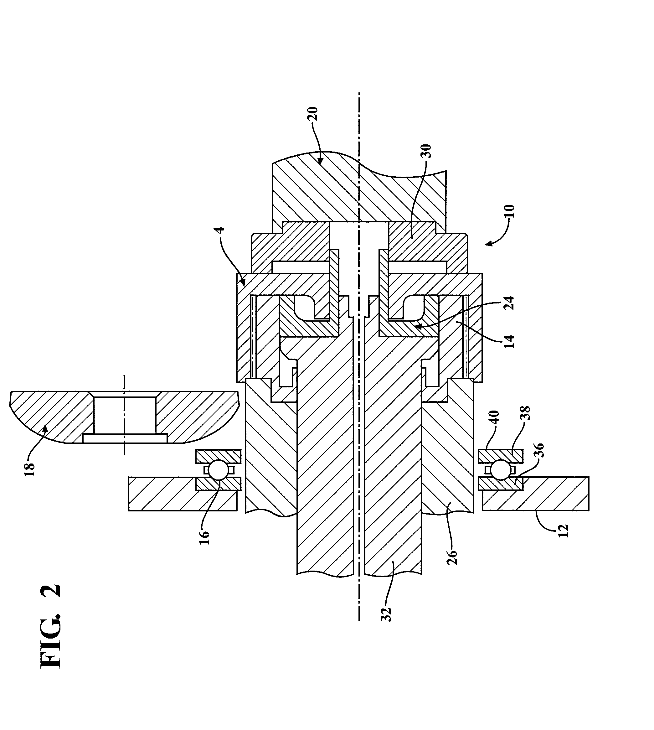
[0023]Referring to FIGS. 1-4 generally, the present invention is directed to a system (apparatus and process) for flow forming a workpiece or pre-form 2 into a final part, generally shown at 4, including helical splines formed by a mandrel during a flow forming process. Flow forming the helical splines allows manufacture of a final part 4 having a one-piece construction including flow formed helical splines. In general, a flow formed final part 4 including helical splines can be automatically stripped from the apparatus while also maintaining the integrity of the final part 4. The final part 4 can have splines that are equally spaced grooves to form a generally helix shape about a central axis.

[0024]A flow-forming machine, generally show at 10, is provided with a stripper plate 12 for removing the final part 4 having ...


PUM

PropertyMeasurementUnit
pressuresaaaaaaaaaa
inner diameteraaaaaaaaaa
outer shapeaaaaaaaaaa

Abstract

A flow-forming machine and method for forming a final part having helical splines. The flow forming machine is provided with a stripper plate for removing the final part having the helical splines therein from the mandrel and a thrust bearing is located between the stripper plate and the final part during stripping of the final part from the mandrel to allow relative motion between the stripper plate and the final part to successfully strip the final part from the mandrel without damaging and while maintaining the integrity of the helical splines of the final part. The ejector driver and mandrel may be rotated in either direction to help in successfully stripping the final part from the mandrel.

Description

CROSS REFERENCE TO RELATED APPLICATIONS[0001]The instant application claims priority to U.S. Provisional Patent Application Ser. No. 61 / 668,271, filed Jul. 5, 2012. The entire disclosure of the above application is incorporated herein by reference.FIELD OF INVENTION[0002]The present disclosure relates generally to the forming of a part having an internal helical spline. More particularly, the present disclosure relates to the removal from a mandrel of a part that was formed on the mandrel and having at least one internal helical spline.BACKGROUND OF THE INVENTION[0003]There if a long history and developed knowledge of the use of flow forming and related processing for making parts including, cylinders and forming cylinders having internal splines typically formed along the length of the cylinder and perpendicular to the base of the mandrel. Forming and processing to form a variety of such objects, including housings, has been developed and improved over the years.[0004]In general, f...

Claims


Application Information

Patent Timeline
Patent Type & Authority Applications(United States)
IPC IPC(8): B21C35/02
CPCB21C35/02B21D22/16B21D45/02B21D53/28
Inventor ABBASSIAN, BAHMANCHRISTIANSEN, LISA
Owner MAGNA POWERTRIAN INC (US)
Learn More