
Bollards

a bollard and lateral technology, applied in the field of bollards, can solve the problems of compromising structural integrity, time-consuming and laborious, and inconvenient excavation of such a floor surface in order to accommodate embedded bollards, so as to reduce the length of the chain, facilitate manual insertion, and reduce the lateral dimension.

Active Publication Date: 2014-01-09
ATG ACCESS
View PDF14 Cites 18 Cited by
  • Summary
  • Abstract
  • Description
  • Claims
  • Application Information

AI Technical Summary

Benefits of technology

This patent aims to create a shoe that has a minimal vertical block, which can be a square or other shape. The shoe is made of resilient rubber or polymer with a hardness of at least 50. The bearing member of the shoe can be made of either rubber or metal. Each insertion of a shoe can reduce the length of a chain of a fully extended ladder by 5-10 mm. The technical effect is to create a shoe that can be easily inserted between ladder links to absorb shocks and minimize the risk of injury.

Problems solved by technology

This is costly, time consuming and damaging to existing ground surfaces.
Excavating such a floor surface in order to accommodate embedded bollards is extremely undesirable.
Structural integrity maybe compromised and the embedding of suitably robust bollards may not be feasible or permissible.
These problems are compounded when the situation requires only temporary placement of a barrier.
Furthermore, when the embedding of barriers within an excavation is required, the existence of obstacles to the intended positioning and linear trajectory of parts of the barrier may prevent the necessary excavation being provided.

Method used


Image

  • Bollards
  • Bollards
  • Bollards

Examples


Embodiment Construction

[0102]In the drawings like articles are assigned like reference symbols. The barriers of the following examples may be surface-mounted shallow-mounted in a shallow excavation within which a foot part is embedded.

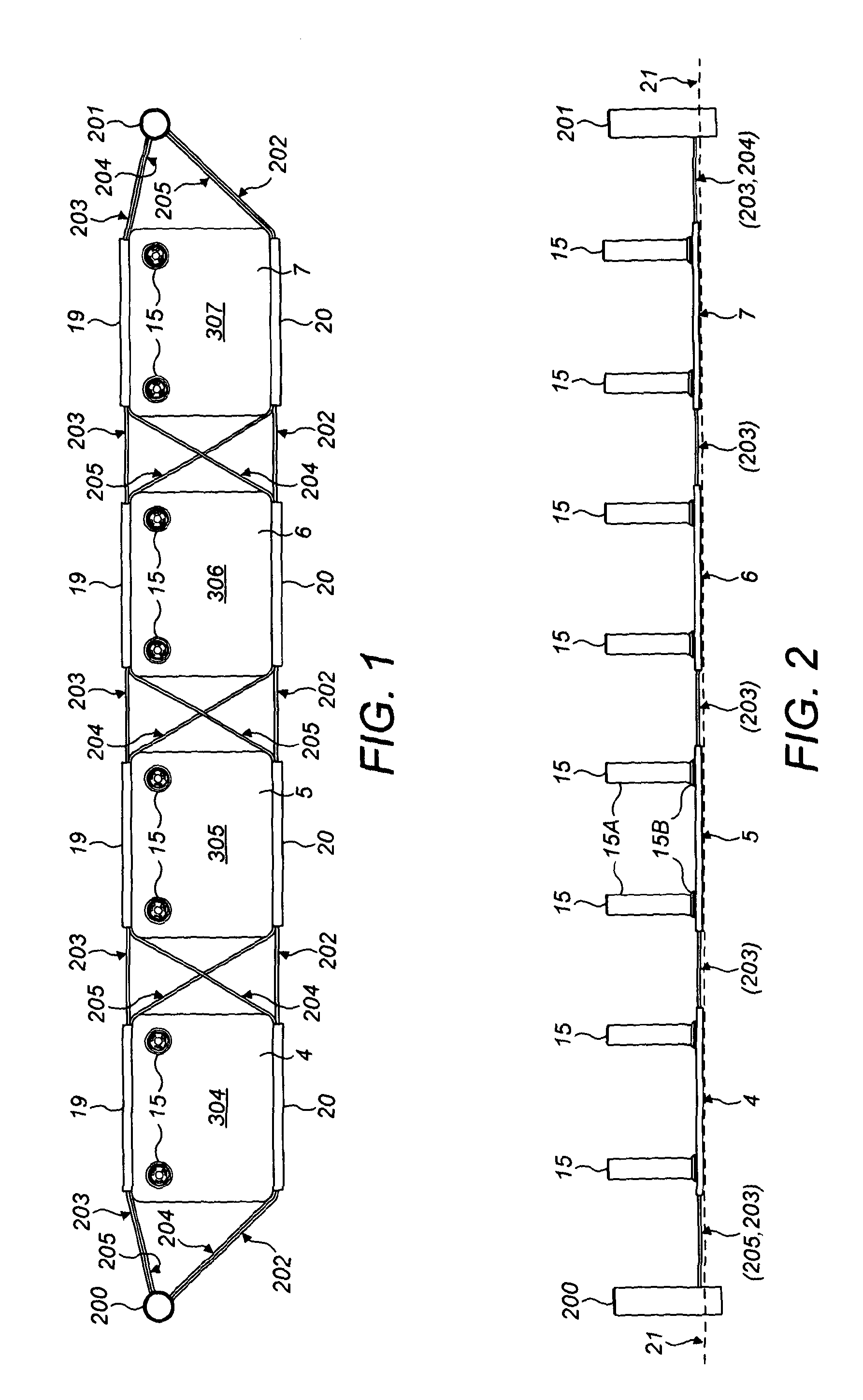
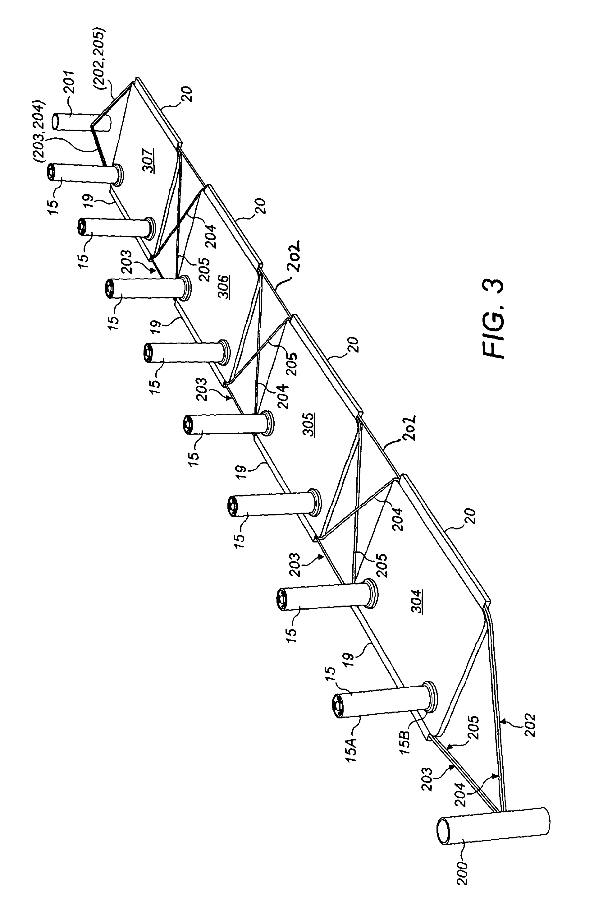
[0103]FIG. 1 illustrates a vehicle impact barrier assembly (1) comprising an array of four separate and separated barrier units (304 to 307). Each barrier unit comprises a foot member (4,5,6,7) including a plate part formed from a steel plate being substantially rectangular in shape and adapted for ground engagement by placement of a lowermost plate surface upon a ground or floor surface. Each of the separate barrier units comprises at least two tubular steel bollard members (15) fixed to the plate part at their bases via a collar (15B) by welding (or other fixing methods, e.g. cement) so as to be upstanding generally in the perpendicular direction from the flat surface of the plate part of respective foot member facing uppermost in use. In other embodiments the bollards may...


PUM


Abstract

A bollard apparatus for use as a vehicle barrier including one or more bollard members, and one or more separate foot members each adapted for ground engagement by placement upon (or shallow-mount embedment within) a ground or floor surface. To each of the foot members is fixed at least one bollard member upstanding therefrom. At least one collar member is positioned within a respective through-opening in a respective foot member wherein the collar member is fixed to the base end of a bollard member and circumscribes the bollard member thereat. The collar member is upstanding from the surface of foot member from which the bollard number is also upstanding.

Description

BACKGROUND[0001]1. Technical Field[0002]The invention relates to bollards. In particular, though not exclusively, the invention relates to vehicular impact barriers and bollards suitable for use in vehicular impact barriers.[0003]2. Description of Related Art[0004]The provision of barriers comprising bollards, particularly vehicle barriers, often requires the permanent fixture, embedding or foundation of bollards within a ground surface in order to provide sufficient robustness and resilience of permanency to the barrier. It is very common that bollards arrayed collectively to provide such a barrier on a ground surface require some degree of excavation into that ground surface to enable each individual bollard of the barrier to be firmly, fixedly and permanently set into the ground to be upstanding from it. This is costly, time consuming and damaging to existing ground surfaces. For example an existing ground surface may comprise a paved area or may comprise a floor surface which is...

Claims


Application Information

Patent Timeline
IPC IPC(8): E01F15/00
CPCE01F15/003E01F13/12E01F9/685
Inventor BALL, ROBERT N.
Owner ATG ACCESS
Learn More