Milling insert

a technology of inserts and milling holes, which is applied in the direction of gear teeth, manufacturing tools, manufacturing apparatus for gear teeth, etc., can solve the problems of difficult control of grinding precision, disproportionately large share of grinding cost of total manufacturing cost of milling inserts,

Inactive Publication Date: 2014-01-09
SANDVIK INTELLECTUAL PROPERTY AB
View PDF47 Cites 28 Cited by
  • Summary
  • Abstract
  • Description
  • Claims
  • Application Information

AI Technical Summary

Benefits of technology

[0009]The present invention aims at obviating the above-mentioned disadvantages of previously known milling inserts and at providing an improved milling insert. A primary object of the invention is to provide a milling insert, which can be manufactured by extraordinary precision in respect of the micro geometry and spatial location of the cutting edge line, without the requisite grinding unnecessarily burdening the total cost of the manufacture of the milling insert. A further object is to provide a milling insert that is especially suitable for gear hobbing and allows frequent insert replacements so as to maintain a good surface quality and good dimensional accuracy of the machined components.
[0011]By forming the cutting edge between, on one hand, a chip surface having a limited width and thereby a limited grinding area, and, on the other hand, a primary clearance surface the width of which is smaller than the extension of the clearance surface between the upper side and the under side, the surfaces needing to be ground to provide extraordinary high dimensional accuracy in respect of the spatial location of the generated cutting edge line are minimized. In doing so, peripheral grinding of the chip surface as well as the primary clearance surface in one and the same set-up is made possible.
[0013]In one embodiment, the width of the chip surface amounts to at most 50% of the width of the primary clearance surface. In such a way, the grinding area of the chip surface is minimized at the same time as the primary clearance surface becomes sufficiently wide to make the cutting edge strong and resistant to the dominant cutting forces.
[0015]In a feasible embodiment, the chip surface of the cutting edge is made plane. In such a way, the grinding becomes simple and can be carried out by means of a plane side surface of a grinding wheel.
[0018]In one embodiment, the under side of the milling insert may also include a second groove, which is running perpendicular to the first-mentioned one. This second groove blocks the milling insert from moving in the direction parallel to the first groove, i.e., in the longitudinal direction of the milling insert, at the same time as the first groove prevents movement of the milling insert laterally.

Problems solved by technology

If said milling insert would need to be ground to provide a good dimensional accuracy of the cutting edge, the total grinding area, i.e., the entire upper side and the entire clearance face adjacent to the cutting edge, becomes so large that the share of the grinding cost of the total manufacturing cost of the milling insert becomes disproportionately large.
Another disadvantage of known milling inserts of the kind in question is of grinding technical nature, depending on there being a difference between face grinding and peripheral grinding.
The fact that grinding of the chip and clearance surfaces of the individual cutting edge is carried out in two different steps means that the precision of the grinding becomes difficult to check and control, in particular in the light of the milling insert during the face grinding step not being kept fixed in a geometrically well-defined position.

Method used


Image

  • Milling insert
  • Milling insert
  • Milling insert

Examples


Embodiment Construction

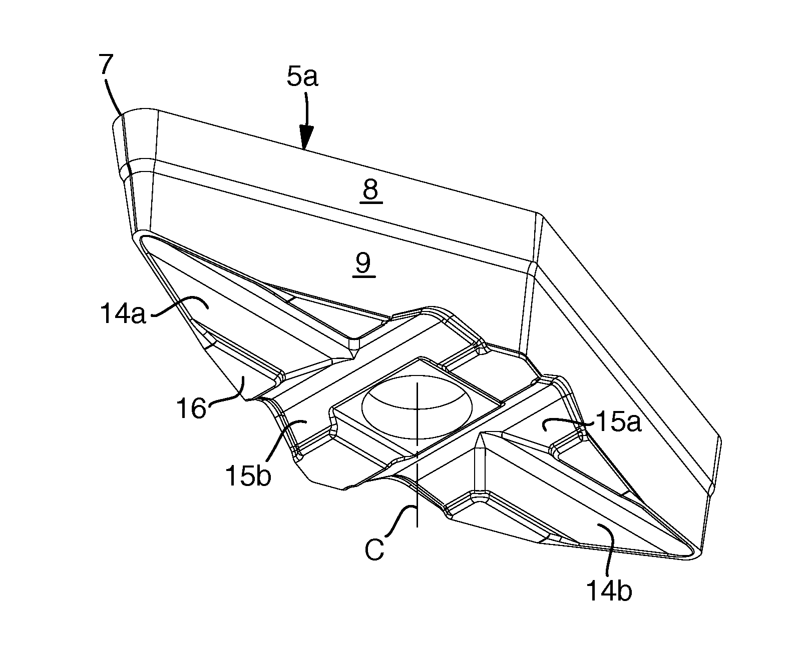
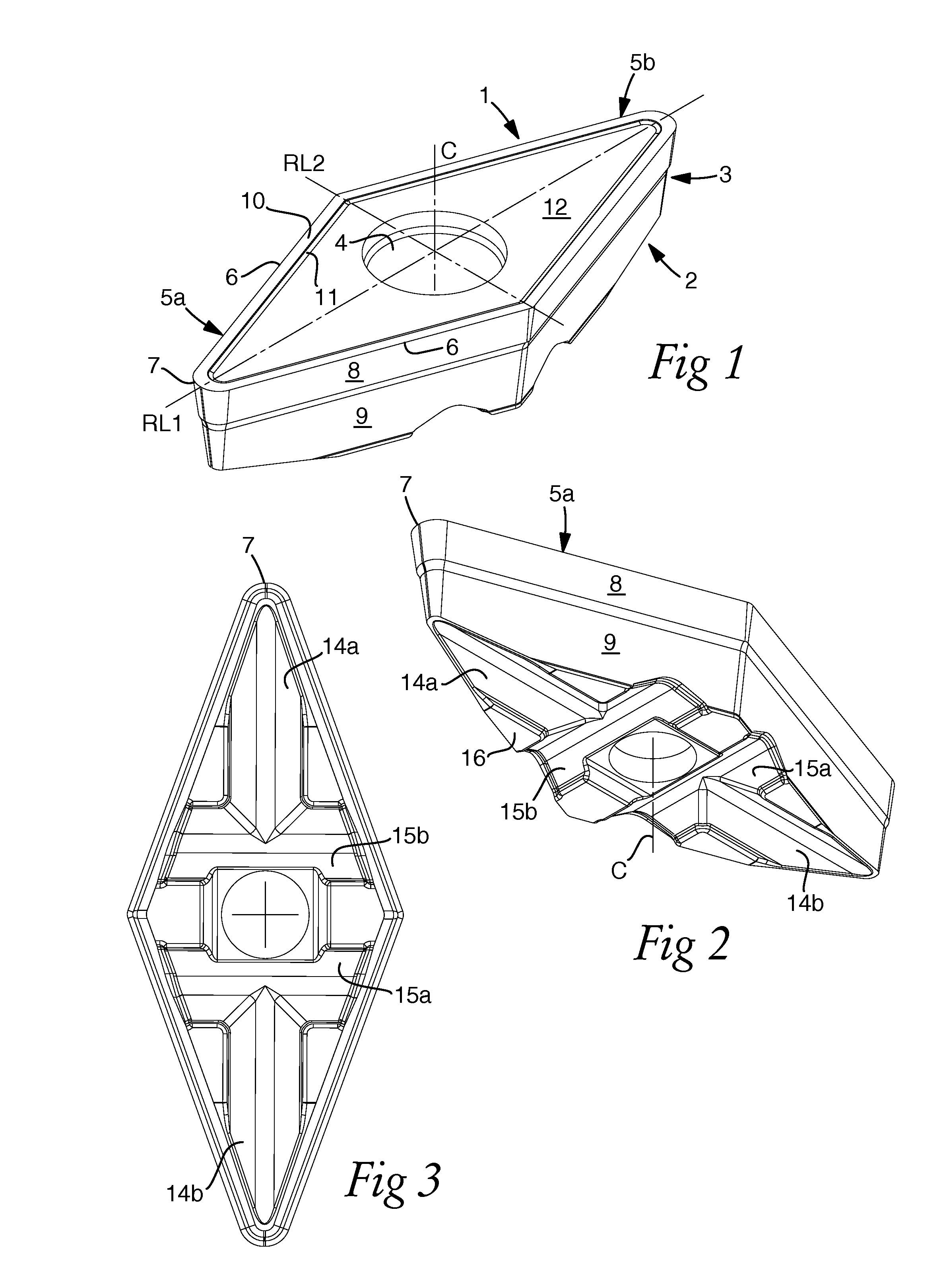
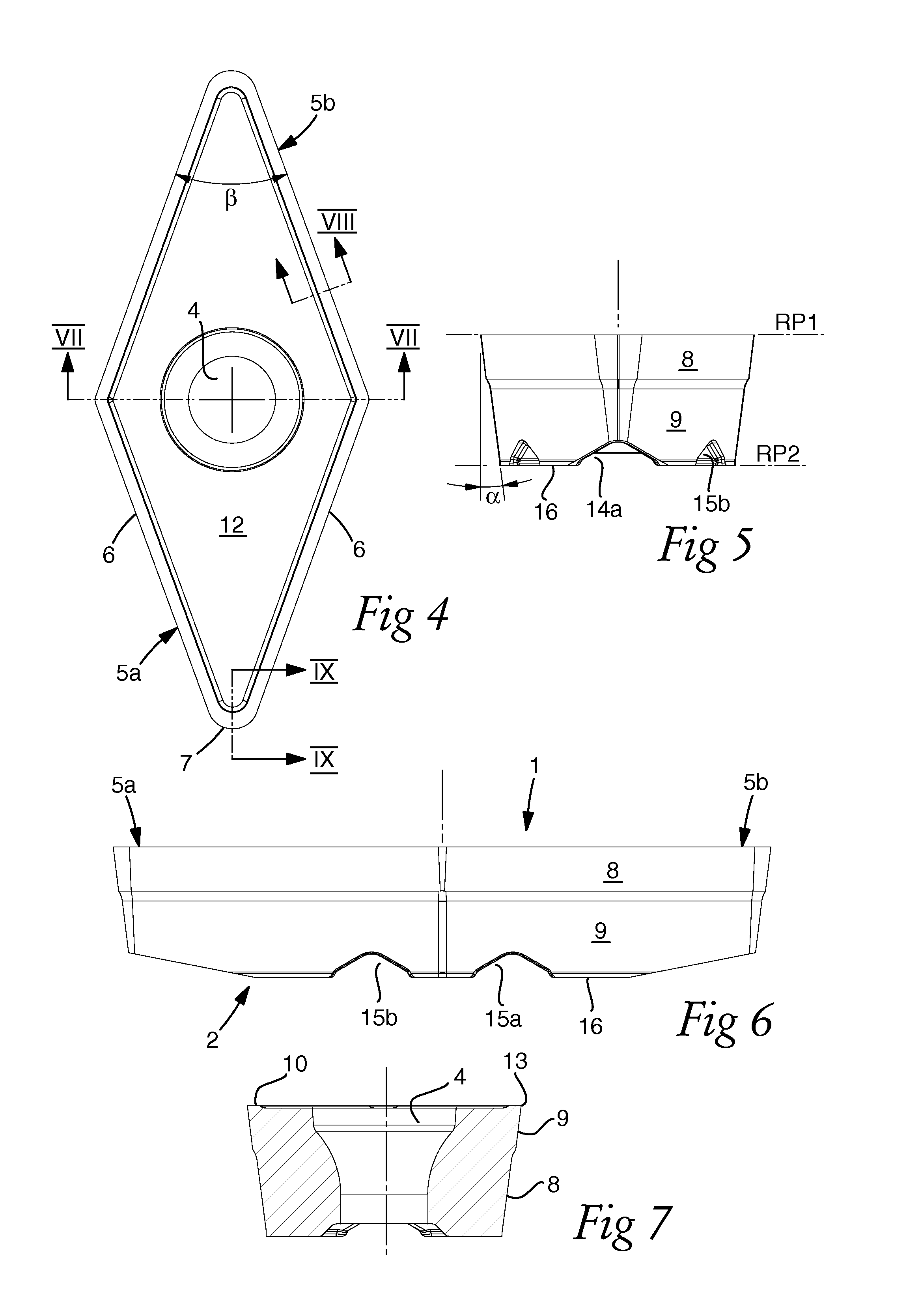
[0031]In FIGS. 1-9, a milling insert made in accordance with the invention is shown, which includes an upper side (also denominated “chip face”) in its entirety designated 1, an under side in its entirety designated 2, and a clearance face that extends between the same and in its entirety is designated 3. Between the upper and under sides 1, 2, a centre axis C of the milling insert extends. This is located in the point of intersection between two straight reference lines RL1, which is a longitudinal axis, and RL2, which is a transverse axis, which reference lines RL1, RL2 form right angles with each other. The axis C also forms a centre axis of a through hole 4 intended to receive a screw for the fixation of the milling insert in a basic body of the tool (not shown).

[0032]In the example, the milling insert is indexable by including two alternately usable cutting edges 5, which are identical in respect of their shape as well as their spatial location in relation to the centre axis C....


PUM


Abstract

A milling insert having an upper side, an under side, a clearance face disposed between the upper and under side, and at least one cutting edge that includes two main edges, which converge toward a nose edge. The cutting edge is formed between two ground part surfaces situated on both sides of a cutting edge line, by on one hand, a primary clearance surface, which is included in the clearance face and is off-plane from a lower, secondary clearance surface, and, on the other hand, a peripheral chip surface, which is included in the upper side and situated on a higher level than a land disposed inside, and which is narrower than the primary clearance surface and has a width of at least 0.3 mm. The milling insert may advantageously be used in milling tools for gear hobbing.

Description

TECHNICAL FIELD OF THE INVENTION[0001]This invention concerns a milling insert of the type that comprises an upper side, an under side, and a clearance face extending between the same, as well as a cutting edge, which is running along a cutting edge line and formed in a transition between the upper side and the clearance face and includes two main edges that converge toward and meet in a nose edge, the milling insert having a positive cutting geometry so far that an angle between the clearance face and a normal to the upper side is acute.BACKGROUND OF THE INVENTION[0002]The invention has its origin in problems that are associated with milling inserts, more precisely such replaceable milling inserts that are included in tools for so-called hobbing or gear hobbing. Gear hobbing is a relatively new milling method by means of which slots can be milled out of the envelope surface of metallic workpieces having a rotationally symmetrical shape with the ultimate purpose of forming ridges, e...

Claims


Application Information

Patent Timeline
Patent Type & Authority Applications(United States)
IPC IPC(8): B23C5/20
CPCB23C5/207B23F21/128B23F21/146B23F21/166B23F21/226B23C2200/085B23C2200/126B23C2200/165B23C2200/365Y10T407/23B23C5/202B23C5/20B23C5/22B23C5/10B23F21/16
Inventor WANDEBACK, GUSTAFJANSSON, JORGEN
Owner SANDVIK INTELLECTUAL PROPERTY AB
Why Eureka
Try Eureka