Eureka AIR delivers breakthrough ideas for toughest innovation challenges, trusted by R&D personnel around the world.

Preswirler configured for improved sealing

Active Publication Date: 2014-01-09
SOLAR TURBINES
View PDF3 Cites 10 Cited by
  • Summary
  • Abstract
  • Description
  • Claims
  • Application Information

AI Technical Summary

Benefits of technology

The patent describes a preswirler for a gas turbine engine and a method of mounting it to a diaphragm. The preswirler has an outer ring with first holes for coupling to a diaphragm, while the diaphragm has outer diameter holes and a mounting portion with inner diameter holes. The method involves inserting bosses into the inner diameter holes and welding them to the diaphragm. Then, an outer diameter coupler and an inner diameter coupler are used to connect the outer ring and the inner ring to the diaphragm, creating a seamless connection for cooling air. The technical effect is improved cooling efficiency and reduced temperature variations in the gas turbine engine.

Problems solved by technology

Portions of a gas turbine engine are subject to high temperatures.
An uncontrolled loss or leakage of air may lead to a loss of efficiency and improper cooling.

Method used


Image

  • Preswirler configured for improved sealing
  • Preswirler configured for improved sealing
  • Preswirler configured for improved sealing

Examples


Embodiment Construction

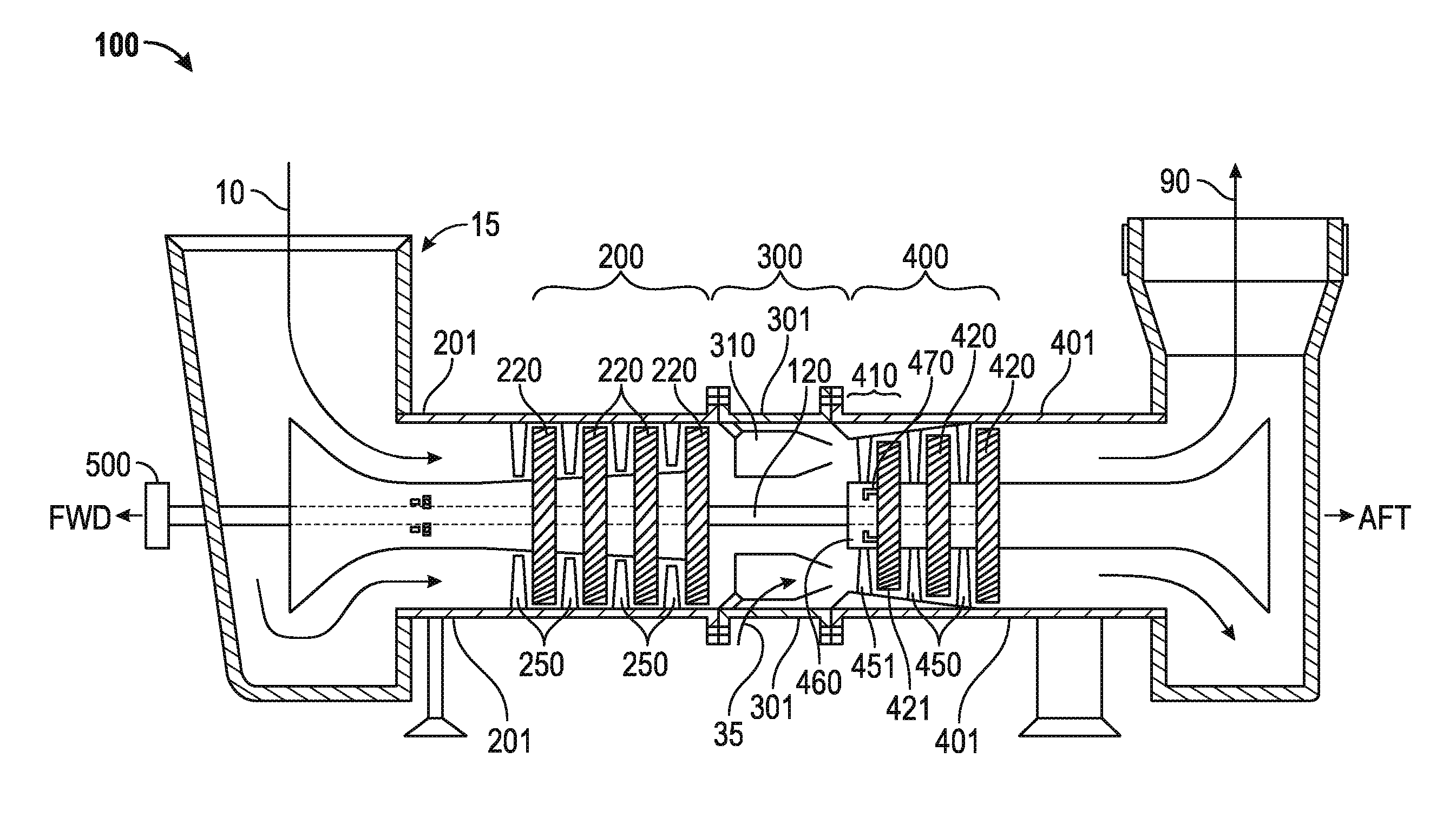
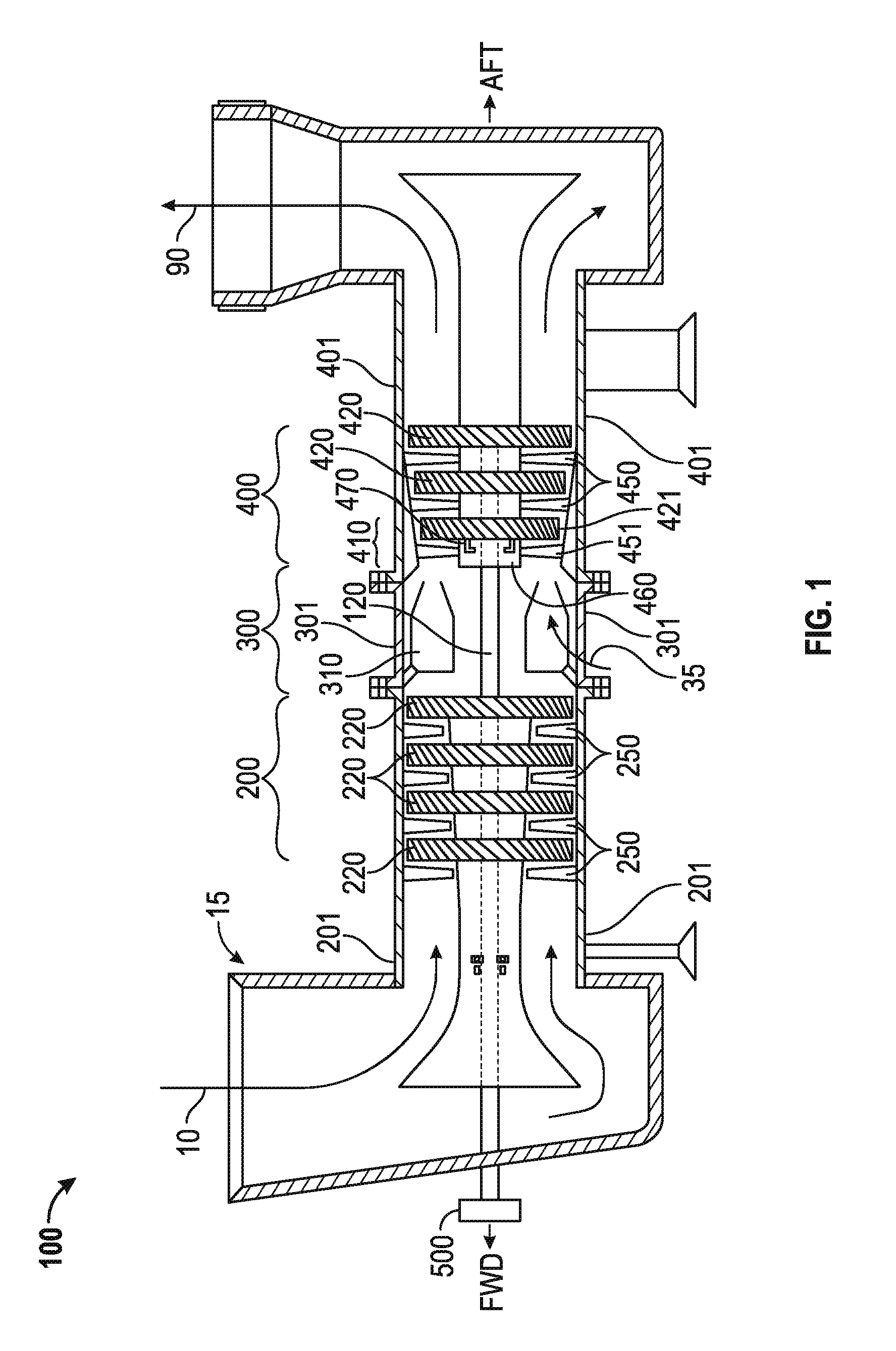
[0011]FIG. 1 is a schematic illustration of an exemplary gas turbine engine. A gas turbine engine 100 typically includes a compressor 200, a combustor 300, and a turbine 400. Air 10 enters an inlet 15 as a “working fluid” and is compressed by the compressor 200. Fuel 35 is added to the compressed air in the combustor 300 and ignited in the combustion chamber 310. Energy is extracted from the combusted fuel / air mixture via the turbine 400 and is typically made usable via a power output coupling 500. The power output coupling 500 is shown as being on the forward side of the gas turbine engine 100, but in other configurations it may be provided at the aft end of gas turbine engine 100. Exhaust 90 may exit the system or be further processed (e.g., to reduce harmful emissions or to recover heat from the exhaust).

[0012]The compressor 200 includes one or more compressor rotor assemblies 220 mechanically coupled to a shaft 120. The turbine 400 includes one or more turbine rotor assemblies 4...


PUM

PropertyMeasurementUnit
Diameteraaaaaaaaaa

Abstract

A preswirler of a gas turbine engine includes an outer ring. The outer ring includes an outer flange with a plurality of first holes, and an outer cylindrical portion extending from the outer flange. The preswirler also includes an inner ring. The inner ring includes an inner flange spaced apart from the outer flange. The inner ring also includes an inner cylindrical portion located within the outer cylindrical portion and a back portion extending from the inner flange to the inner cylindrical portion. The inner ring further includes a plurality of second holes.

Description

TECHNICAL FIELD[0001]The present disclosure generally pertains to gas turbine engines, and is more particularly directed toward a preswirler configured for improved sealing to a diaphragm within a gas turbine engine air ducting system.BACKGROUND[0002]Gas turbine engines include compressor, combustor, and turbine sections. Portions of a gas turbine engine are subject to high temperatures. In particular, the first stage of the turbine section is subject to such high temperatures that the first stage is cooled by air directed through internal cooling passages from the compressor. In one such passage, air is directed through the diaphragm of a gas turbine engine and into the preswirler. An uncontrolled loss or leakage of air may lead to a loss of efficiency and improper cooling.[0003]U.S. Pat. No. 4,730,978, to W. Baran, Jr., discloses a manifold structure for supplying cooling air to a turbine rotor of a gas turbine engine. The manifold is secured to the engine frame by a plurality of ...

Claims


Application Information

Patent Timeline
IPC IPC(8): F01D9/02F01D25/00B23P11/00F01D25/12
CPCF01D5/081F01D9/041F01D25/12F01D25/28F05D2260/14Y10T29/49826Y10T29/49945
Inventor MEYER, CHRISTOPHER J.KIM, HYUN D.LIN, TSUHONRAMIREZ, EDWARD T.
Owner SOLAR TURBINES
Why Eureka
Eureka Blog
Learn More