Robot control apparatus and robot control method

a robot control and robot technology, applied in the field of robot control apparatus and method, can solve the problems of low rigidity of the reducer, easy vibration, and significant affecting of the takt time, and achieve the effect of improving the durability of the robot without significantly affecting the takt tim

Active Publication Date: 2014-01-09
CANON KK
View PDF23 Cites 39 Cited by
  • Summary
  • Abstract
  • Description
  • Claims
  • Application Information

AI Technical Summary

Benefits of technology

[0009]In view of the above, the present invention provides a robot control apparatus and method capable of improving durability of a robot without significantly affecting the takt time.

Problems solved by technology

On the other hand, the robot includes a speed reducer, a belt, a bearing, and the like as transmitting components for transmitting a drive force from a drive source (actuator) to a joint, but particularly the speed reducer generally has low rigidity, and hence vibration easily occurs when steep acceleration and deceleration is performed.
The technology described in Japanese Patent No. 4335286 can protect the robot, but when the overload is detected during the robot movement, it is necessary to proceed to the processing of protecting the robot, which leads to a problem that the takt time is affected.
Further, the technology described in Japanese Patent Application Laid-Open No. 2011-167827 can reduce the vibration to be generated during the robot movement, but even if the vibration is reduced, the load torque that acts on the transmitting component is not always reduced.
In other words, for example, as the rigidity of the transmitting component becomes higher, the vibration is reduced, and hence the movement speed may increase by the calculating method described in Japanese Patent Application Laid-Open No. 2011-167827, but when the transmitting component is brittle, the transmitting component may not be able to withstand the increased movement speed.
That is, even when the trajectory to reduce the vibration is calculated, the load torque to be applied to the transmitting component is not always reduced, and hence there is a problem in that the durability of the robot is not always improved through the reduction of the vibration.

Method used


Image

  • Robot control apparatus and robot control method
  • Robot control apparatus and robot control method
  • Robot control apparatus and robot control method

Examples


first embodiment

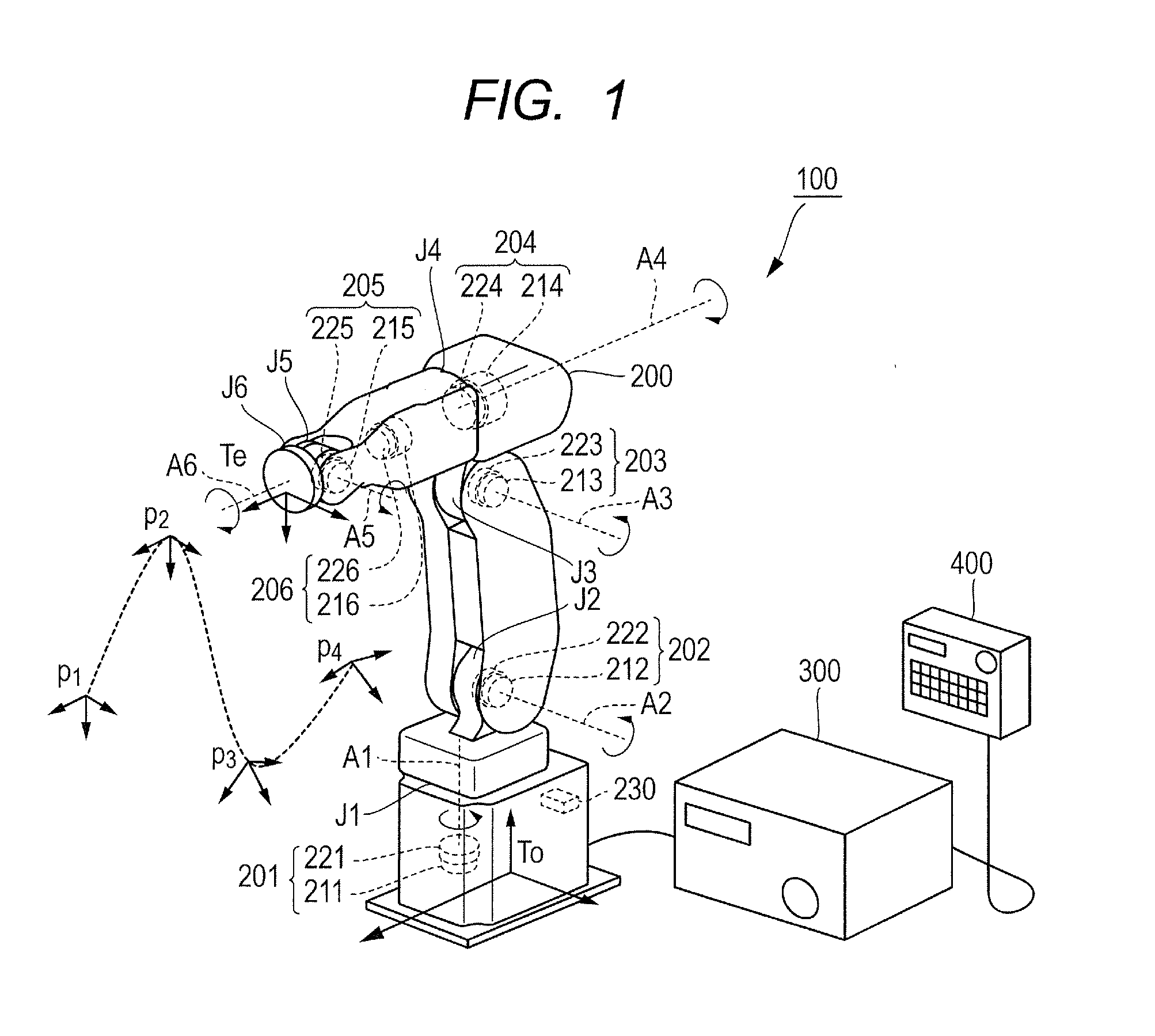
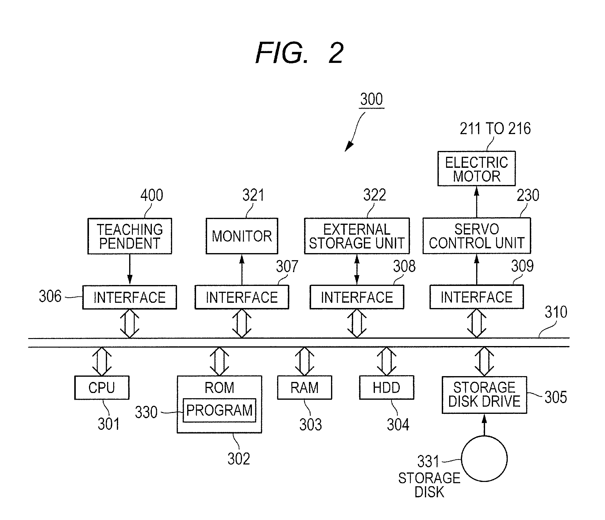
[0034]In the following, a first embodiment of the present invention is described with reference to FIGS. 1 to 9. First, a schematic configuration of a robot apparatus is described. As illustrated in FIG. 1, a robot apparatus 100 includes a robot arm 200 serving as a multi-joint robot, and a robot control apparatus 300 for controlling the robot arm 200. Further, the robot apparatus 100 includes a teaching pendant 400 serving as a teaching apparatus for sending data of multiple teaching points to the robot control apparatus 300. The teaching pendant 400 is operated by human, and is used to specify movement (trajectory) of the robot arm 200 and operation of the robot control apparatus 300.

[0035]In this embodiment, the robot arm 200 is a 6-joint robot, for example. The robot arm 200 includes multiple (six) actuators 201 to 206 that rotationally drive joints J1 to J6 about joint axes A1 to A6 thereof, respectively. The robot arm 200 can direct its hand (tip of the robot arm) in an arbitr...

second embodiment

[0065]Subsequently, a second embodiment of the present invention, which is obtained by partially changing the above-mentioned first embodiment, is described with reference to FIGS. 10 to 13. Note that, in the description of the second embodiment, parts similar to those of the first embodiment are denoted by the same reference symbols, and description thereof is omitted.

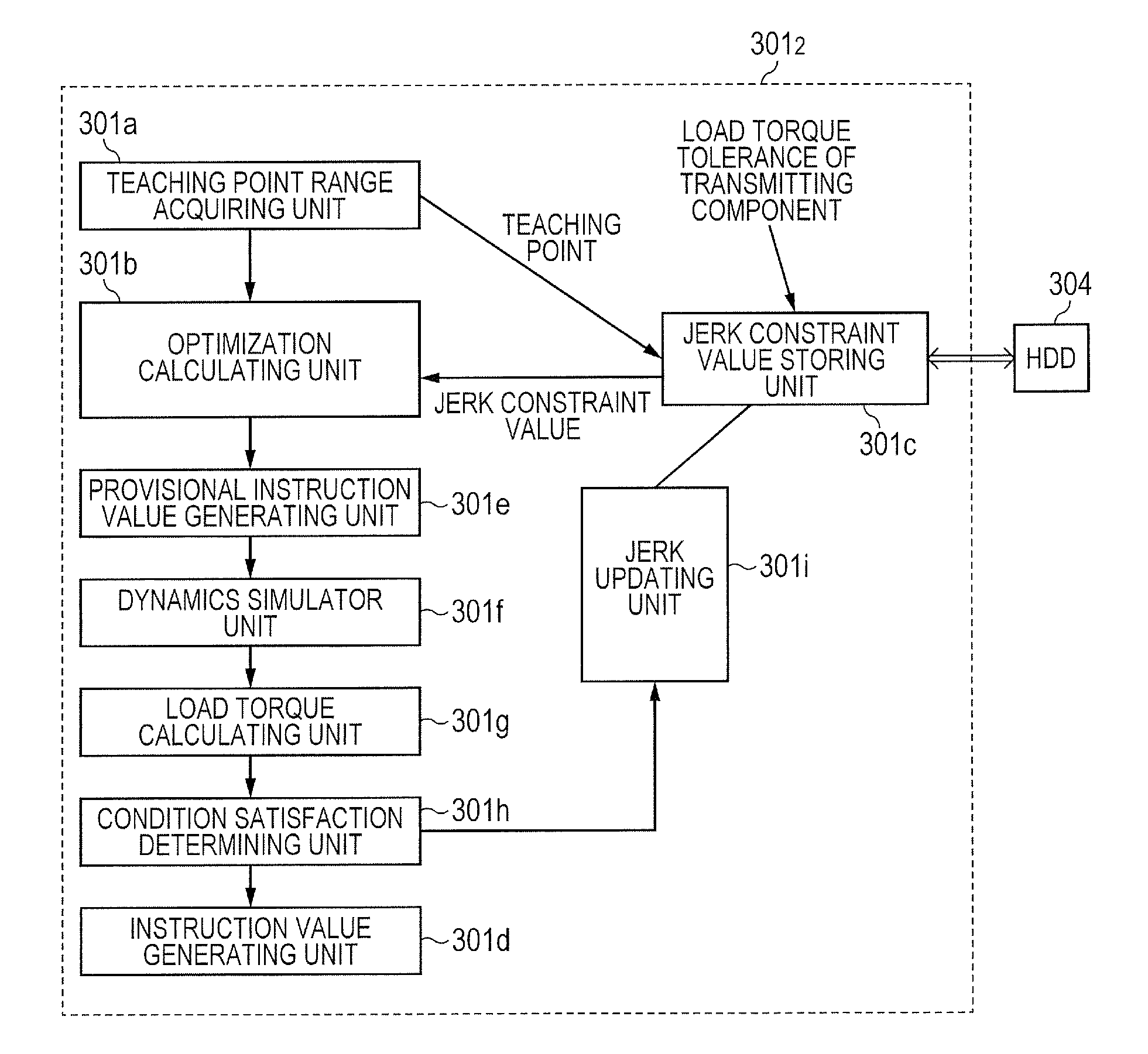
[0066]The second embodiment differs from the first embodiment in that the robot control apparatus 300 according to the second embodiment is configured to simulate, based on the calculation of the load torque using a dynamics model, whether or not the instruction value calculated in the optimization calculating unit 301b satisfies the constraint conditions. As a result of the simulation using the dynamics model by a dynamics simulator (movement simulator), in a case where the constraint conditions are not satisfied when the robot arm 200 is driven with the instruction value, the constraint conditions (jerk constraint v...

third embodiment

[0078]Subsequently, a third embodiment of the present invention, which is obtained by partially changing the above-mentioned first embodiment, is described with reference to FIGS. 14 and 15. Note that, in the description of the third embodiment, parts similar to those of the first embodiment are denoted by the same reference symbols, and description thereof is omitted.

[0079]The third embodiment differs from the first embodiment in that the robot control apparatus 300 according to the third embodiment is configured to calculate the torque generated when the robot arm 200 is actually driven, and learn the constraint conditions when the constraint conditions are not achieved.

[0080]Specifically, as illustrated in FIG. 14, a CPU 3013 serving as the calculating unit in the third embodiment functions as the following units in addition to the teaching point range acquiring unit 301a, the optimization calculating unit 301b, the jerk constraint value storing unit 301c, and the instruction val...


PUM


Abstract

A robot control apparatus controls a robot arm driven by transmitting drive forces to joints from respective electric motors so that the robot arm follows a specified trajectory, based on an instruction value instructed against the electric motors. A movable range of the robot arm is divided into multiple spaces, and constraint conditions including a constraint value of a jerk for each joint, which is determined so that a load torque applied to a transmitting component of the drive force falls within an allowable range in the multiple spaces, is calculated in advance. The constraint conditions are stored in a storage unit. A calculating unit generates the instruction values for the electric motors based on the trajectory by solving an optimization problem that uses the constraint conditions stored in the storage unit as an inequality constraint.

Description

BACKGROUND OF THE INVENTION[0001]1. Field of the Invention[0002]The present invention relates to a robot control APPARATUS and method for controlling a robot arm that is driven to follow a specified trajectory, based on an instruction value to be instructed against a drive source corresponding to each of multiple joints.[0003]2. Description of the Related Art[0004]In recent years, industrial robots that perform assembly and the like in a factory have been demanded to adapt to production speed improvement and complex movement, and have been demanded to increase their movement speed. In order to increase the movement speed of a robot, steep acceleration and deceleration is required in joint drive. On the other hand, the robot includes a speed reducer, a belt, a bearing, and the like as transmitting components for transmitting a drive force from a drive source (actuator) to a joint, but particularly the speed reducer generally has low rigidity, and hence vibration easily occurs when st...

Claims


Application Information

Patent Timeline
Patent Type & Authority Applications(United States)
IPC IPC(8): B25J9/16
CPCB25J9/1664B25J9/1633G16Z99/00B25J9/06B25J13/00B25J19/06G11B3/34G05B2219/40519G05B2219/40454
Inventor NAKAJIMA, YOHJI
Owner CANON KK
Why Eureka
Try Eureka